Using a MOSFET as a switch is generally pretty simple. Make the gate voltage sufficient with respect to the source and current flows through the channel. However, if you are switching higher voltages, you may need some additional circuitry to protect the device’s gate and possibly the microcontroller driving the whole thing, too. [Lewis] discusses high voltage switching in the latest in his series of videos dealing with MOSFETs. You can see the video below.
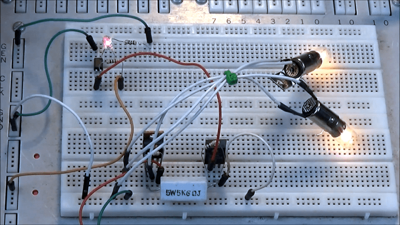
You’ll see in the video a breadboard setup driving a 50 V load and also a higher-voltage H-bridge. There are three major topics covered: Using an optoisolator, using a gate bleeder resistor, and using a zener diode to limit gate voltage.
Of course, an optoisolator isn’t necessary with or without the high voltage, as long as everything works well. It can, however, prevent high-frequency noise from conducting from the FET channel through the gate acting as a capacitor. It can also be useful for saving the controller if there is a failure that shorts the channel to the gate.
The bleeder resistor isn’t specific to high voltages, either. Because the gate is practically an open circuit at DC, it is a good idea to add a resistor like this so that when the gate drive is off, you don’t have to wait for the charge on the gate to dissipate. In addition, the resistor offers some protection against electrostatic discharge (ESD) damage, since the ESD will tend to flow through the resistor instead of punching through the gate oxide on the device.
The zener sees service in two ways. At first, the circuit uses it to derive 12 V from the 50 V supply. However, in a later incarnation, the design uses it as a clamp to keep a P-channel’s gate at 12 V. These are both important because the maximum rating of the gates is 20 V.
Although the devices in the video are IRF630s and IRF9630s, the principles apply to lots of different kind of FETs. Just remember what you kind you have and understand the datasheet before you finalize your design.
If you want something more basic, there are plenty of tutorials. We’ve even looked at high-side switches in detail.


I very much enjoy Lewis Loflin’s electronics videos. Thanks for pointing out another good one.
Damn it! I was hoping for kilovolt-level switching. Love this guys work though
Take a look at this cascode HV stack: https://en.wikipedia.org/wiki/Cascode#Other_applications
How inductive are those bulbs? Seems like a reverse diode across the load would be a good idea.
Common misconception. Bulbs are basically a pure resistive load.
For small, lightly inductive loads you can rely on the body diode of the (power) FET. That being said, diodes are cheap; put one across the FET or load for paranoia sake.
The body diode won’t help you when switching off an inductive load. It will spike voltage at the drain, and the diode will be blocking.
… until it doesn’t anymore and you chase the magic smoke out :(
Stray inductance in the leads can be enough to blow up a driver FET by exceeding Vdsmax, especially if you’re using it in chopper/PWM mode. The freewheel diode *must* be present.
(if you have a full H-bridge, the body diodes in the pair-of-devices-that-didn’t-just-turn-off can save you, but the energy will be pumped into your DC bus so watch that voltage climb if the “load” is a motor going downhill)
Why is necessary a zener diode? For example, in p channel schema what about if you make a resistor divider with 15K and 5.2K resistors? I mean: change 15k to 22k and 5.2k to 47k (or 2.2k and 4.7k) and eliminate the zener diode. With 50V you will have about 16V in Vgs. You can adjust resistors to get Vgs=12V if you want. Then my question is …. is mandatory the zener with this resistor divider ? thanks
The zener diode caps the voltage, the voltage divider takes a ratio of whatever the input voltage is. So the zener diode also acts as overvoltage protection