
If you want to have your part designs fabricated, you’re going to need to provide the manufacturer with a technical drawing. Yes, 3D printers and many modern machine tools rely on toolpaths created from 3D models. But, there is a good chance the manufacturer will be recreating the 3D model in their own system, instead of using the one you provided. Or, they may use traditional manual machining and not touch a 3D model at all. More importantly, the technical drawing gives them vital information on how closely they need to adhere to your dimensions in order for you to accept the parts.
On a technical drawing, the dimension that you want is called the nominal. But, no manufacturing is ever perfect, so you have to allow some wiggle room in what you’ll accept. That wiggle room is called tolerance. Maybe your part could be a little longer than specified and it wouldn’t affect the functionality. Maybe it could be a little shorter—or either. Specifying a tolerance is necessary, because it tells the manufacturer exactly how much wiggle room you’re giving them.
But, tolerances can introduce unforeseen consequences if you’re not careful. The wiggle room provided by tolerances is absolutely necessary, but if you don’t use them properly you can easily end up with unusable parts, even if the manufacturer followed your instructions to the letter. That usually happens because you have multiple tolerances being added together, which is called tolerance stacking.
Compounding Problems
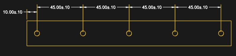
Take a look at the dimensions of the part shown above, can you see the problem? At first glance, you might assert that this tells the manufacturer that the right-most hole can be between 189.90 and 190.10 mm from the left edge of the part. In reality, this actually tells them that it can be anything from 189.50 to 190.50 mm. That’s because each dimension is based on the feature before it, which is flexible by 1/10th of a millimeter in either direction. That compounds with each new feature, and the tolerances stack to eventually end up with a lot more wiggle than you likely intended.
Now, it’s entirely possible that a total potential variation of 1mm may not make your part unusable. But, even if that’s the case, this is still bad practice because it’s unclear if that is your intention or not. The entire purpose of the drafting discipline is to remove ambiguity when communicating a part design, and tolerance stacking is very ambiguous. If your right-most hole can have a 0.50mm tolerance in both directions, that should be explicitly stated.
Using Ordinate Dimensions
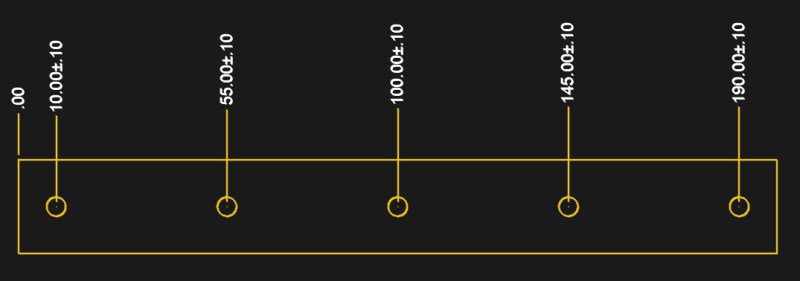
How do you definitively specify that without stacking your tolerances? In this example, the simplest solution is to use ordinate dimensions, which all reference a single solid origin point. The edges of the part are hard edges, and are likely what you want the interior features to be measured from. Therefore, you can use ordinate dimensions, like below, from the left or right edge so that every hole has a non-flexible reference and avoiding tolerance stacking.
Unfortunately, ordinate dimensions won’t work in all situations. For instance, the part below has features that are arranged radially. The dimensions—and therefore tolerances—are in degrees, not a distance like with millimeters. But, this is still a case of tolerance stacking, and the first and last holes could end up being anywhere from 132 to 138 degrees apart.
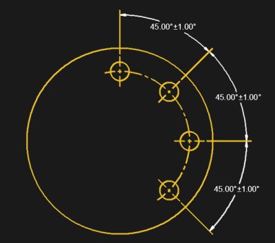
In that situation, the prudent solution would be to base each dimension off of a single geometric reference point, like the top dead center. So, the second hole would be 45°, the third would be 90°, and the fourth would be 135°. But, once again, that’s only a solution to another specific example; what you really need is a firm understanding of the problem, and to use critical thinking to recognize it and solve it in your own technical drawings.
Don’t Make Them Guess
Tolerance stacking happens when a feature’s placement is measured from another feature that has a position that could change slightly. In some cases, you may want that. In the example above, it’s possible that, in your design, the third and fourth holes being 45° apart is more important than their position relative to the first hole, or the part in general. You’re the only one who knows what’s necessary for your part to function properly, and it’s the manufacturer’s job to simply follow your technical drawing as closely as possible.
You always need to keep that concept in mind as you’re drafting your technical drawings. Ask yourself how much wiggle room you’re willing to give the manufacturer. But, at the same time, ask yourself what that wiggle room is based off of. Maybe a particular feature needs to fall within a specific tolerance from the edge of the part—or maybe it’s more critical that it be located precisely in relation to a neighboring feature. Only you know.
The purpose of a technical drawing is to tell the manufacturer exactly how to make your part, and to do so without any potential confusion. If they follow your drawing to the letter, you can’t then reject a delivery of 1,000 parts because they didn’t correctly guess your intent. In most cases, the machinists won’t know or care how your design actually works, they only care about how precisely they can adhere to your drawing. So, it’s up to you to fully understand what your drawing is telling them, and how to avoid problems like tolerance stacking.


Interesting…
FWIW,
There is a story (Urban Legend?) about a cooperation between Ford Motor Company and Mazda to both make a transmission in the U.S.A and Japan, respectively. Ford and Mazda had “sister” vehicles in production such as the Ford Ranger and Mazda B2000 pickups.
The pre-production parts at each plant were audited for accuracy, first in the U.S.A, and then in Japan. When the auditors inspected the parts made in Japan, they thought their measuring instruments had failed because they found no deviation between the parts and their drawings. They asked the Mazda engineers about this and were told something to the effect; “we don’t do tolerances, the drawings indicated these dimensions, and that is how we built them.”
Definitely an urban legend. Process if ok if it’s within 2/3rds of std. deviation. Going for extra precision where not required is a sign of fisting and waste of time.
It’s a true story. Read into the background about legendary-guy W Edwards Deming:
https://en.wikipedia.org/wiki/W._Edwards_Deming
Deming’s teachings and philosophy are clearly illustrated by examining the results they produced after they were adopted by Japanese industry,[3] as the following example (called the Ford-Mazda study) shows. Ford Motor Company was simultaneously manufacturing a car model with transmissions made in Japan (by Mazda) and the United States (by Ford). Soon after the car model was on the market (c. 1950),[4] Ford customers were requesting the model with Japanese transmissions over the US-made transmissions, and they were willing to wait for the Japanese model. As both transmissions were made to the same specifications, Ford engineers could not understand the customer preference for the model with Japanese transmissions. Finally, Ford engineers decided to take apart the two different transmissions. The American-made car parts were all within specified tolerance levels. However, the Japanese car parts were virtually identical to each other, and much closer to the nominal values for the parts—e.g., if a part was supposed to be one foot long, plus or minus 1/8 of an inch (300 mm ± 3 mm)—then the Japanese parts were all within 1/16 of an inch (1.5 mm), less variation. This made the Japanese cars run more smoothly and customers experienced fewer problems.[5][6]
There is a nice deviation on this story, some American factory ordered some parts from Japanese factory and stipulated that the defect rate should be no more than five in every 100 . The Japanese sent the Americans two boxes, one with 95 parts in pristine condition and another box with a load of rusty old spanners. Who says the Japanese have no sense of humour?
The version I always heard was a company ordering a box of 1000 ICs or whatever component from Japan, and specifying a <5% defect rate.
When they received the box, it had a separate plastic bag in it with 50 of the components, and a note attached reading "We aren't sure why you requested defective items, but for your convenience we've packaged them separately."
yeah, thats’ the one!
I just watched a documentary about the Roland TR-808 drum machine. At the end, they talked to the original designer. He explained that the reason for both the 808’s distinct sound and its short shelf-life is they used a defective transistor to get a price break. Since the factory they bought it from upped their standards and obviously couldn’t repeat the defect, the 808 was discontinued.
One man’s trash….
If it was <5%, there should have been at most 49.9999999999* parts.
Which reminds me, when I worked for a hard disk drive company, the failure rate on the manufacturing line was a closely guarded secret, (I was not privy to the actual rates), just as long as enough good drives could be built to remain profitable. They may have had a 66% failure rate on some products (culled out before shipping, of course!).
Must be Seagate.
wd in the 90’s before they bought their way out of incompetence
I’ve taken a lot of hard drives apart. Seagates are the most likely to have internal sharpie writing.
Not a statistically relevant sample, but my Seagate drives always seem to fail. I only buy them for vendor diversity in arrays. At least that’s easier with SSD arrays.
The ability to cut cost by producing exactly what was required, and as a bonus get rid of some scrap metal at the customers expense.
They are so efficient even their humor saves them money.
Codswallop. They may have worked to tighter tolerances than the auditors, but there is no such thing as exactly perfect.
You my friend do not know my wife.
You sir, have earned every point the interwebz will ever give me. You made my day, thank you.
My favorite Japanese tolerances urban legend involved a Japanese railroad company that bought a French caternary system of overhead wires for an electric railroad. And started experiencing a lot of vibration related failures that these never seemed to have in France. Eventually they determined the problem was that the specs called for installing the support poles 10 meters apart. The French took that as a guideline and put the poles somewhere between 9 and 11 meters apart. The Japanese had been spacing them as closely to 10 meters apart as they could get, resulting in resonances that spread across the whole wire. The installation directions had to be changed to “Install support poles 9 to 11 meters apart, and ensure no two adjacent sections of wire are within 0.5 meters of the same length”.
The urban legend might be based on a true story (I cannot remember accurately if it was in the book “The Toyota Way”, or in the book “The machine that changed the world”) where the Japanese fabricators at Toyota set up their production systems to provide parts to very tight tolerances.
Using SMED techniques (Single Minute Exchange Of Die) they set up production areas that would be able to make parts to highly accurate tolerances, without needing to spend a lot of time doing so. Think about how when you go to home depot and ask them to cut several lengths of wood for you, and they set the stopper on a chop saw and can cut out multiple lengths of equal size for you in just under two minutes, and then adjust the cutting tool to meet the specifications of the next customer. That tool setup is simple enough, is quick to adjust, and can repeatedly and reliably produce many parts to many specified lengths, but with very little variance between the parts being produced. Compare this to how well you would do to produce 10 pieces at the same length using just a marker, a measuring tape and a hacksaw. Ironically Ford Motors pioneered stuff like this between 1915 and 1918, but never managed to get it right or implement it until after Toyota’s lean manufacturing techniques were made public.
This relates to the tolerance story in the following manner. The Americans allowed a 1/8″ tolerance to the length of the drive-shafts in their cars (Assume then that the Americans expected a 4′ drive shaft to be between 4′ and 4′-1/8″). 1/8″ tolerance is carpentry level precision, but due to the fabrication methods being used at the time by the Americans, this was part of the expected tolerances they could use. To evaluate the production standards that Toyota was using, they purchased several Toyota cars and took them apart to evaluate their tolerances, and found that they were produced exactly to the specified length (almost no variance between parts).
Also, most driveshafts at that time would have been connected to a slip yoke at one end to accommodate the movement of a live axle rear suspension. Such an application doesn’t really NEED a precise length on the driveshaft. The U-joint angular alignment is pretty important.
The joys of gd&t, How to get parts that “work” from parts that fail inspection… Reference planes and datums are key, ordinate dimensions are nice depending on your manufacture’s ability to ready drawings…
The plural of datum is data, not datums.
datum, data, and datums are all acceptable plurals.
daters!
Judging by the sudden rush of comments ???? , I doubt if many people here have had this problem. My normal approach is to ask the manufacturer “what is the process you’re gonna use?”. Then i ask them “what are the tolerances?” Then I would probably ask them “what sort of things go wrong during the process? “.
Once, I was buying some steel and the guys had no idea how accurate the saw was and I had to measure it myself. Their response was “We are not precision engineers mate”. My reply was: ” well you might not be, but your saw is and it cuts to 0.2 mm accuracy if you use the automatic feed”.
Next up: two-by-fours that are exactly two inches by four inches. Since when is raw stock supposed to be precision cut…?
Max …. now you really have hit a raw nerve …… fume …. rant …… The machinery can easily cut raw stock to within 1 mm but the tolerances are so wide they always hit bang on the lower limit to save cash. Dunno where you live, but here a two by four can come out very reliably ridiculously small, like 1 3/4″ by 3 1/2″ ……. Wankers!
I thought that was because they cut it while it’s green and dry it after. Which is probably faster in that order, due to increased surface area.
Here in the US, 2×4 is like “1/4 pound of beef before cooking”. Originally stated size was raw size before drying and planing, and the finished product varied in size. Presumably a few vendors exploited that variation and undersized their lumber a bit. Since the consumer cares about a consistent finished size, the industry switched to a controlled finished size, but kept the original label, so a 2×4 spec is 1-1/2″ x 3-1/2″. So if you think of 2×4 as a label, rather than 2″x4″, you’ll sleep better.
If you still want to grind your teeth: The S4S 1×8 at the big box store is shipped planed to the spec’d .75″, but is so badly cupped that its useful thickness is often far less when replaned flat. (I get unsurfaced boards from the local lumber mill instead, when I can. Even before planing it’s usually flatter than the big box stock. It’s also cheaper and the wood doesn’t look like it’s just from a pub brawl.)
https://en.wikipedia.org/wiki/Lumber#North_American_softwoods
“two by four” is a nominal unfinished dimension, finished “two by fours” have, for a long time, been smaller due to post cutting finishing.
When sending my first PCB for mass production/assembly I wrote up a doc like this with diagrams of where everything should go, measurements, photographs of what it should look like exactly at various stages of assembly, I was simply afraid of anything going wrong on my first run and wanted to cover every possible eventuality. Gotta put yourself in the shoes of a person who has never seen that thing you’ve been slaving over for months. they don’t know the little facts you take for granted. Fabs appreciate this stuff a lot, makes their lives a lot easier.
I can agree with this.
I have made some cheap PCB’s before for my stuff, and the odd error happens here and there.
I had some prototypes and a small production run done at work, and the people at the fab literally went through every single drawing and datasheet and line-by-line to make sure that they assembled everything exactly as we needed.
It was fascinating to learn how the other side works, and to see how much more work I need to do to make sure that the next one goes through better.
The humbling part was when I was doing some of the final testing and commissioning on the parts we received back. They were assembled perfectly except for a few components mounted blocking some future connectors… It turned out that I had not considered them and glossed over the descriptions for that line, and the fab had mounted them exactly as I had requested.
I once worked in a company that did commisionary work for other companies. One day they got a master part to reproduce say 100 times(i don´t know exactly), well, they did but the machinist screwed up one diameter of the part. What to do? Trash the 100 pieces? Nope, they decided to turn the diameter of the master down to the dimension of the parts. Oh what a fun the lawyers had.
I use to run operations at a small CNC shop, when we ordered bar stock that was cut, we would state something like 500pcs .5 x .5 x 3″ +/- .50 – we never ever expected the sawn pieces to be to size, and we always ordered oversize as one should machine all faces of a part.
When it came to tolerances we would pre-inspect the drawing prior to quoting, then check back with client for stacked tolerances as well as loosing up some. We explained to the client at a +/- .010″ on an exterior part length will save them money vs a .005″ same for internal radius’s smaller than a .375″ requires smaller tools, slower feeds and increased costs.
You see we dont have a problem holding .001″ tolerance for delivered parts, we just happen to have a lot of scrap parts, ultimately, customers pays the cost.
You would not believe the cost reduction by increasing irrelevant tolerances and enlarging some hole sizes. Also another thing we found is a lot of new or self taught designers didnt understand design for manufacturing. — That is, if you design a part that is a 2″ wide because you thought material comes 2″ wide, guess what, we are buying a bar of stock that is 2.5″ wide, 1-so we can hold it, 2-so we can machine all sides and make it 2″ wide. That means the client is paying for .5″ more material.
So some notes that will reduce your manufacturing costs:
1: open up irrelevant tollerances
2: increase hole sizes
3: increase internal radius’s
4: design product overall dimensions under nominal stock sizes by .100″
5: talk with the manufacture as Teg mentioned above
ok, sorry for the long post
I normally review all of our drawings before they go out for fabrication, my favorite is calling angles out to three decimals for a welded pipe…no matter how many times you explain that just because the CAD calculates the angles out that far, doesn’t mean you have to call it out like that.
No need to apologize for the post, it was insightful. Thank you for the post.
For the examples given modern Geometric Tolerancing is the way to fly, circular tolerance zones and positional tolerances exist exactly to solve this particular issue. Your dimension and tolerance scheme communicates a lot about design intent, for the liner hole pattern example above, the hole to hole dimension and tolerance might be the best way to do it if what ever part that attaches to that part interfaces with only 2 adjacent holes, where we need the parts to fit well but the absolute positioning of the assembly isn’t ±.10mm important, sure the ordinate dimensioned part will work fine but it will cost more and/or have more rejected parts.
I can definitely say I have experienced similar stuff at one of my former employers. They were an OEM of large machinery made up of two related companies that got bought out and mashed together, but they only kept one of the machine shops, and it happened to be the machine shop for the company that used looser default tolerancing. When they tried to make one of the sister/tighter tolerance company’s machines, they fabbed all the parts and put it together and the machine wouldn’t run correctly. It was a mess, their machine shop literally could not fabricate replacement parts or new parts for the tighter tolerance design whatsoever. Any time they had to fab replacements or make a new machine of that design they ended up having to sub out parts manufacturing and have some of their old final assembly guys put it together or it wouldn’t work.
Sounds like they kept the cheaper of the 2 machine shops, then got what they paid for…
They kept the non-union shop with a cheaper (smaller) building, and then sold off all the high-end machine tools to make a few quick bucks rather than move them across town.
So you got it about right.
My favorite story is always of the intern who was assigned to do a small flange, but nobody checked the drawing and just sent it out to get made. Part comes back costing 10x more because they didn’t call out any fillets and it had to be wire EDMed to get the perfect right angle on all the internal corners.
That’s only because the machine shop you use didn’t have a set of square end mills.
Hasn’t anybody herd of “true position tolerance”?
This discussion is pretty basic, might be the first thing a junior draftsman learns.
First, I agree with you, this solves a few issues, however, if a, for lack of a better word, a maker, first time engineer, self taught CAD user, if they cant figure out basic 2D tolerances and stacking, I my no means expect them to understand true position. Best to always consult the print with the shop. sometimes on quick simple prototypes I just send 3D model and call out +/- .01 and then tighten as we get further in the design. Parts always diverge by 3rd 4th revision.
My neighbors company did stainless steel fabrication. I had him quote some parts for me. All my tolerances were +/-.005″. He said He could only hold +/- 0.001 on his laser cutter. Great sense of humor. The laser could cut 3/4″ stainless to +/-0.001″ tolerance.
Just one more pass of the surface grinder….
I was making a pile of exhaust ports for a client, they specified a +0.05mm tolerance and on the first batch I got down to just above what was required and used black marker on the surface then slowly dropped the head just until the marker started to scuff off. Let the surface grinder run for a couple of passes and presto.. bang on size. well within about 0.003mm to 0.009. all the parts came back and the company kicked up a stink because when their guy used a vernier to check them they were undersized according to them.
Sent the parts out to another engineering company and confirmed they were all bang on size. then the company came back saying they needed them +0.05 larger. Lol. guess that’s what you get for going the extra mile for a customer.
Did they specify +0.05mm tolerance or ±0.05mm tolerance? if the former, maybe they thought that it meant (stupid them) that you should make it +0.05mm larger than specified.
First thing I did when I had control of the development budget was have all the calipers calibrated by a CSA/UL certified lab. Cost a lot of money that could almost never be justified to the bean counters, except for the priceless confidence that all our measurements were accurate to the specs on the stickers and the occasional dispute settled with a simple, “Our calipers are certified calibrated… are yours?”
I have a fun tolerance story.
For our capstone project I designed an electromagnet for an aerospace application (Magnetorheological fluid controlled damping system). The problem we had was to optimize the electromagnet for strength and weight (strongest electromagnet at the lightest weight) so I wrote a genetic algorithm based optimization program to design it for me.
The geometry was simple and easy to build, but the program optimized the results to 5 decimal places (I was so proud of myself at that moment). I had not yet internalized the concept of tolerancing.
We handed it to our university fabricators, and we waited for 3 weeks, getting really nervous. The geometry was not complicated and our fabricators were in a union dispute with the university. We wondered if we were getting blown off. We went in to confront the machinists and they looked at us like freaks asking us why we had demanded such tight tolerances. They had one guy who was an aerospace machinist who had to take out the gauge blocks to fabricate the damn thing, and they were freaked out about this particular project, and took it as a personal challenge to complete.
The real shitter on this is
a) The setup would have been fine with a +- 0.015″ tolerance (and we would have gotten our part in 2 days)
b) When coiling wires for an electromagnet, you need to tolerance your design under the assumption that the wires are 10% larger in diameter than indicated in order to properly handle space packing issues with the wire coils. I failed to do that, so the part had to be tossed, and I had to pay another machinist to make my part for me with the new (corrected) dimensions.