How Precise Is That Part? Know Your GD&T

How does a design go from the computer screen to something you hold in your hand? Not being able to fully answer this question is a huge risk in manufacturing because . One of the important tools engineers use to ensure success is Geometric Dimensioning and Tolerancing (GD&T).

A good technical drawing is essential for communicating your mechanical part designs to a manufacturer. Drafting, as a professional discipline, is all about creating technical drawings that are as unambiguous as possible, and that means defining features explicitly. The most basic implementation of that concept is dimensioning, where you state the distance or angle between features. A proper technical drawing will also include tolerances for those dimensions, and I recently explained how to avoid the pitfall of stacking those tolerances.

Dimensions and tolerances alone, however, don’t tell the complete story. On their own, they don’t specify how closely the geometric form of the manufactured part needs to adhere to your perfect, nominal representation. That’s what we’re going to dig into today with GD&T.

Continue reading “How Precise Is That Part? Know Your GD&T”

How—And Why—To Avoid Tolerance Stacking In Your Technical Drawings

If you want to have your part designs fabricated, you’re going to need to provide the manufacturer with a technical drawing. Yes, 3D printers and many modern machine tools rely on toolpaths created from 3D models. But, there is a good chance the manufacturer will be recreating the 3D model in their own system, instead of using the one you provided. Or, they may use traditional manual machining and not touch a 3D model at all. More importantly, the technical drawing gives them vital information on how closely they need to adhere to your dimensions in order for you to accept the parts.

On a technical drawing, the dimension that you want is called the nominal. But, no manufacturing is ever perfect, so you have to allow some wiggle room in what you’ll accept. That wiggle room is called tolerance. Maybe your part could be a little longer than specified and it wouldn’t affect the functionality. Maybe it could be a little shorter—or either. Specifying a tolerance is necessary, because it tells the manufacturer exactly how much wiggle room you’re giving them.

But, tolerances can introduce unforeseen consequences if you’re not careful. The wiggle room provided by tolerances is absolutely necessary, but if you don’t use them properly you can easily end up with unusable parts, even if the manufacturer followed your instructions to the letter. That usually happens because you have multiple tolerances being added together, which is called tolerance stacking.

Continue reading “How—And Why—To Avoid Tolerance Stacking In Your Technical Drawings”

How To Reverse Engineer Mechanical Designs For 3D Modeling

If you’re interested in 3D printing or CNC milling — or really any kind of fabrication — then duplicating or interfacing with an existing part is probably on your to-do list. The ability to print replacement parts when something breaks is often one of the top selling points of 3D printing. Want some proof? Just take a look at what people made for our Repairs You Can Print contest.

Of course, to do that you need to be able to make an accurate 3D model of the replacement part. That’s fairly straightforward if the part has simple geometry made up of a primitive solid or two. But, what about the more complicated parts you’re likely to come across?

In this article, I’m going to teach you how to reverse engineer and model those parts. Years ago, I worked for a medical device company where the business model was to duplicate out-of-patent medical products. That meant that my entire job was reverse engineering complex precision-made devices as accurately as possible. The goal was to reproduce products that were indistinguishable from the original, and because they were used for things like trauma reconstruction, it was critical that I got it right.

Continue reading “How To Reverse Engineer Mechanical Designs For 3D Modeling”

3D Printer Tool Changer Gives You Access To Lots Of Extruders

The benefits of having a 3D printer with multiple extruders are numerous: you can print soluble support material for easy removal, print a combination of flexible and rigid filament, or simply print in different colors. Unfortunately, traditional multi-extruder setups have some serious drawbacks, even aside from the cost.

Usually, the extruders are all mounted next to each other on a single carriage. This increases the mass, which can cause print quality issues like shadowing. It also reduces the printable area, as each extruder needs to be able to reach the entire area. All of this means that the design becomes more and more impractical with each extruder you add, and that’s why it’s uncommon to see more than two extruders on a printer.

Over on Hackaday.io, [rolmie] has come up with a very practical (and affordable) solution to this problem. He has designed a tool changer that gives the printer the ability to switch out hot ends on the fly. The system is very similar to the tool changers we see on CNC machining centers: tools (the hotends) are stored on a rack, and a tool change in the G-code sends the carriage over to the rack to drop off the old hotend and pick up a new one.

The benefit of the design is that both the mass and volume of the carriage are kept to a minimum, while allowing you to use many different hot ends. Each hotend’s settings can be configured individually, and you can even use different models of hotend altogether (maybe one model works better for PLA, while another is better for ABS). The design is still in the prototyping stage and needs some refinement, but it’s a very promising proof of concept that seems like it could be implemented fairly easily into most 3D printer models.

Continue reading “3D Printer Tool Changer Gives You Access To Lots Of Extruders”

Latskap Semi-Automatic Liquor Cabinet

A well-stocked liquor cabinet is a necessity for the classy gentleman or gentlelady who likes to entertain. Having the proper spirits and mixers on hand to make anything from a martini to a sidecar is always a solid way to ensure guests have a good time at your cocktail party. In the past, a beautifully crafted cherry or walnut liquor cabinet was enough to impress visitors with your affluence. These days, if you don’t want to look like a pauper, you have to take it a step further.

[Elias Bakken] and his uncle [Mike Moulton] have decided to take liquor cabinets into the 21st century with a semi-automatic liquor cabinet called Latskap. The project is still in progress, and in the prototyping stage, but their build log on Hackaday.io is showing a lot of potential. It shouldn’t be long before they have a fully functional prototype finished.

Continue reading “Latskap Semi-Automatic Liquor Cabinet”

A Hypnotizing Interactive Art Piece For Visualizing Color Theory

Digital color theory can be a tricky concept to wrap one’s mind around – particularly if you don’t have experience with digital art. The RGB color model is about as straightforward as digital color mixing gets: you simply set the intensity of red, green, and blue individually. The result is the mixing of the three colors, based on their individual intensity and the combined wavelength of all three. However, this still isn’t nearly as intuitive as mixing paint together like you did in elementary school.

To make RGB color theory more tangible, [Tore Knudsen and Justin Daneman] set out to build a system for mixing digital colors in a way that reflects physical paint mixing. Their creation uses three water-filled containers (one each for red, green, and blue) to adjust the color on the screen. The intensity of each color is increased by pouring more water into the corresponding container, and decreased by removing water with a syringe.

An Arduino is used to detect the water levels, and controls what the user sees on the screen. In one mode, the user can experiment with how the color levels affect the way a picture looks. The game mode is even more interesting, with the goal being to mix colors to match a randomly chosen color that is displayed on the screen.

The practical applications for this project may be somewhat limited, but as an interactive art piece it’s hypnotizing. And, it may just help you with understanding RGB colors for your next project.

Continue reading “A Hypnotizing Interactive Art Piece For Visualizing Color Theory”

Bespoke Processors Might Soon Power Your Artisanal Devices

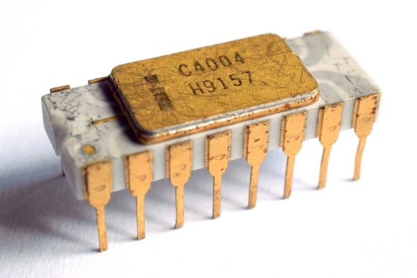
Modern microprocessors are a marvel of technological progress and engineering. At less than a dollar per unit, even the cheapest microprocessors on the market are orders of magnitude more powerful than their ancestors. The first commercially available single-chip processor, the Intel 4004, cost roughly $25 (in today’s dollars) when it was introduced in 1971.

The 4-bit 4004 clocked in at 740 kHz — paltry by today’s standards, but quite impressive at the time. However, what was remarkable about the 4004 was the way it shifted computer design architecture practically overnight. Previously, multiple chips were used for processing and were selected to just meet the needs of the application. Considering the cost of components at the time, it would have been impractical to use more than was needed.

That all changed with the new era ushered in by general purpose processors like the 4004. Suddenly it was more cost-effective to just grab a processor of the shelf than to design and manufacture a custom one – even if that processor was overpowered for the task. That trend has continued (and has been amplified) to this day. Your microwave probably only uses a fraction of its processing power, because using a $0.50 processor is cheaper than designing (and manufacturing) one tailored to the microwave’s actual needs.

Anyone who has ever worked in manufacturing, or who has dealt with manufacturers, knows this comes down to unit cost. Because companies like Texas Instruments makes millions of processors, they’re very inexpensive per unit. Mass production is the primary driving force in affordability. But, what if it didn’t have to be?

Professors [Rakesh Kumar] and [John Sartori], along with their students, are experimenting with bespoke processor designs that aim to cut out the unused portions of modern processors. They’ve found that in many applications, less than half the logic gates of the processor are actually being used. Removing these reduces the size and power consumption of the processor, and therefore the final size and power requirements of the device itself.

Of course, that question of cost comes back into play. Is a smaller and more efficient processor worth it if it ends up costing more? For most manufacturers of devices today, the answer is almost certainly no. There aren’t many times when those factors are more important than cost. But, with modern techniques for printing electronics, they think it might be feasible in the near future. Soon, we might be looking at custom processors that resemble the early days of computer design.