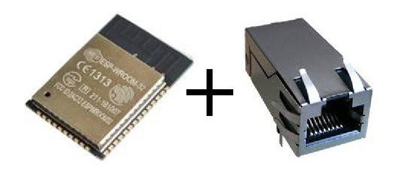
Since its introduction years ago, the ESP-8266 has taken over the world. It’s the chip inside thousands of different projects, and the basis for dozens of different IoT thingamadoos. The follow-up to the 8266, the ESP-32, is even more capable. It has a ton of peripherals inside, including an Ethernet MAC. What’s that? Yes, it’s possible to put Ethernet on an ESP-32, and give an IoT board PoE. That’s what [Patrick] is doing for his Hackaday Prize project, and it’s an awesome idea.
This build began as you would expect, with an ESP-32 module attached to one side of a board with some breakouts for the GPIOs and a USB to Serial chip. The tricky part here is the PoE part of the Ethernet, which requires MagJack Ethernet connectors, a flyback transformer, and a PoE-PD controller. These were expensive parts, and the design of such a board requires some thinking — you need isolation across the transformer, and proper ground planes for this mess.
There’s something slightly brilliant about using an ESP-32 in a wired configuration. Far too often, we see these modules used as wireless nodes in a sensor net. The battery consumption is significant, and all those makers are adding USB power input to their fancy WiFi sensor nets. If you’re running wires for power anyway, why not add Ethernet and do away with all that mucking around with WiFi setup. It’s a great project, and one of the better entries in this year’s Hackaday Prize.


Other then being a cool hack, why! Might as well kust use a proper micro with a mac. Unless he wants to make a cheap AP for the other sensors, but then its more of a money saving thing.
If you are not using the wifi of the esp32 its just a soso chip imo
Why? I’ll turn that around and ask you: why not?
What “proper micro” should I have used instead?
Think about it: the ESP32 has both WiFi and an Ethernet MAC. You could just as well ask: why use it for WiFi if it has an Ethernet MAC? It’s only because WiFi use has been more common up till now that this question came up in your mind. If it’s a soso chip, why even use it for WiFi? There are other WiFi micros out there.
Bottom line is: the ESP32 is a popular target chip in the maker community, has a big community, has many development platforms ported to it, is cheap and works pretty well. I really would like to hear from you what “proper micro” would have been a better option. That’s not a rhetorical question, I’m genuinely curious.
Dont get me wrong it is much appreciated that you designed and are sharing this.
What i mean however, the esp was popular for enabeling wifi on a super low budget which of course is what makers and hackers a like love.
But now we have this ethernet enabled chip which makes the wifi mostly useless.
As to it being a soso chip, the while propriatery/blob sdk is what makes it a meh platform. I understand the reason for having it, wireless regulations are a pain and hiding the details in blobs make it ‘safe’.
Anyhow without the wifi need, therebare tons ofnreally good micros, stm32 based, efm32 surely aswell, atmegas etc etc etc. Just look what riot-os for example runs on.
POE very cool thing for doing iot. I just dont get why on an wifi enabled chip, its like adding fancy rimms on an airoplane and use it for highway driving ;)
Oh I now understand better where you’re coming from. I agree having a binary blob for WiFi in there when not using WiFi would be annoying. Don’t know if it can be removed if you’re not using WiFi.
I realize there are some great other micros, but for something like this I need to follow the community, and the ESP32 happens to be very popular. I don’t think I’d find the same audience if I did this with an STM32 or EFM32 I’m afraid.
I don’t know why you mention ATMega in the same breath with those great chips though. I’d get the community if I did that, but I’d have to call it PoE-PoS if I did that. ;)
It’s simple, if one wants to develop an ESP32 based IoT product, you want to include ethernet as a SEPARATE option…
Whoa there bud! I Wholeheartedly agree about hardwired Ethernet being better than Wifi, BUT do NOT dismiss POE for ATMega and STM32 so quickly please! POE comprises TWO legitimate forms after all – pukka 48v ACTIVE POE, phantom feed (needing Magjacks) needed for Gigabit use with 1000 baseT, AND just plain old fashioned 2 pair 10 baseT/100 baseT POE (Blue/Blue-White pair +ve; Brown/Brown-White pair -ve) low voltage 3v3 (??) thru 5v, 12v to 24v POE injection onto . POE single and multiport injectors are:-
Cheap as chips (both types!)
Readily available in multiple forms from multiple sources
Easy AND simple to implement
Are simple and easy to use with odd-ball voltages from a wall wart when needed – e.g. 7.5v or 9v
SIMPLE to centrally locate and monitor in a comms rack
EASY to fit beautifully into the concept of a SINGLE long distance comms & power connection
Can EASILY be used with EXTERNAL, low cost 48v to low volt supplies but need external magamp isolators for Gigabit (rarely, if EVER, needed on ATMegas or any other micro)
Can be provided as a standard 24volt POE feed centrally with local mini-buck converter units as required (also readily available in multiple forms from eBay and elsewhere)
The concept of the ESP8266/ESP32 is fine for those who want to risk their network/s being compromised security-wise, but absolutely USELESS for SERIOUS IOT where control of potentially EXPENSIVE consequence devices through hacking, blocking or neutralising/nullifying exists. It is FAR too cheap and easy to screw up a WiFi network with a tiny pocket sized, battery powered de-author – not to hack into a network necessarily but to corrupt, ruin or prevent its correct operation! Thus, potentially screwing up burglar alarms, security cameras, garage door openers, heating and electrical control, lighting (2 weeks away with some git having messed with the lighting automation system can leave you with a HEFTY electricity bill)!!!
I’m simply amazed at the complete LACK of proper awareness AND/OR blase attitude to such possibilities from the tech community generally. They all seem to dismiss the possibilities as non-existent! In a domestic environment it is ESSENTIAL to keep the prospect of external tampering to an absolute minimum – why then risk that by opening up to SIMPLE interference from cheap and easily available devices off eBay? To me it’s just NUTS! WiFi should be PURELY for mobile units, like phones and tablets, or outdoor remote sensors or devices not easily (or safely – earth ground potential difference) and NOT for fixed location internal devices.
Hard wiring is the way every single one of the tech savvy crowd should be going. I have a medium sized 3 bed semi – 3 bedrooms, 1 kitchen, 1 utility room, dining and living rooms and 1 attached garage. I am already pushing 36 ports JUST for standard generic use network points, ALL with Cat 5e and some Cat 6a. Flood wiring is something that ought to be mandated in new builds even if it is only to lay cable to suitable points and empty back boxes with blank faceplates. WiFi becoming the defacto standard in houses is bloody ridiculous and stems from lazy cheapskate builder and electrical installer practices.
The above are my NOT so humble opinions born of over 45 years practical field experience and a network user, installer and troubleshooter from the earliest days of Ethernet (big 0.5 inch diameter orange coaxial cable with massive transceiver modules!!)
What if I want to create a wireless bridge for something without a WiFi MAC? (Ie… my Chinese Ruida laser). And want to use the chip’s WiFi AND Ethernet?
A laser is a fixed device. WiFi, due to its bandwidth being shared amongst ALL connections, SHOULD be reserved for mobile devices, like phones, tablets etc. OR those low bandwidth data burst remote devices like outdoor sensors.
It makes zero sense whatsoever to connect large stationary devices via WiFi. A cable is simple, reliable, far more secure, and rarely, if ever, subject to interference. It is also VASTLY simpler to troubleshoot than a wireless connection. A simple tester can prove the viability of the link between devices in literally seconds. The same cannot be said for WiFi.
Using WiFi to connect devices like printers or CNC machines, for example, things that remain in one place, is just lazy & nuts … run a cable! Fine for just two or three devices at home. But with the increasing use of IOT using Wifi (why?), even with V6.0, it will not be able to cope before long and latency will be hit quite hard, quite quickly due to contention for connections … not good for time sensitive IOT!
The bandwidth (V6.0) may well be higher but why do you think we changed from “hubs” (shared connectivity, equivalent to WiFi) to crossbar switches (point to point)?
The ESP32 _IS_ a micro with a MAC. Did you forget that Wifi is built on top of the same protocols as Ethernet? It is also NOT a ‘soso chip’. Most versions are dual processor, which is nice to begin with, but it also has a separate ‘ultra low power’ processor that can monitor an ADC, I2C, or the internal temperature while the main processors are in deep sleep, and it can wake the main processors via timer or whenever you program it to. And it consumes less power in deep sleep mode than the ESP8266. Then you add in all the peripherals that are built in, and I wouldn’t call that ‘soso’
Pardon me for missing the point, but you’re saying there’s a separate Ethernet MAC and a Wifi one? Why? Why is there an Ethernet MAC in there at all, when pretty much the point of the ESP, and surely the reason most are sold, is for Wifi?
Or is Patrick taking the Wifi MAC and somehow diverting it through the device’s pins where it can connect straight to the usual magnetics? In which case why did they allow THAT?
This is different from the time Benchoff told us a MAC had been “discovered” in the ESP8266 but it was actually being bit-banged in software, right? By CNLohr, the god of banged bits.
FWIW I’ve used some ESP32 projects at events where there are a lot of devices competing for Wi-Fi and the ESP32, or at least the implementation I was using, was not very good at coping with the number of other devices nearby announcing their presence.
I was aware that the ESP32 had the necessary and wondered about adding PHY ethernet to get round that. It would be very useful for some specific use cases.
Despite of how “crude” those ESP-xx came to market (in terms of documentation, examples, etc), I love the fact that some people will put great effort to make peripherals and code work. Sense of community at its best (and this fellow may as well score some prizes at Hackaday after all).
That’s true of the ESP8266, but not of the ESP32, where Espressif has been pretty good about providing documentation (ESP-IDF is also *really* nice to use). I think the weak documentation for the 8266 was largely due to Espressif being caught by surprise at how popular it became with hackers and they have since put a good bit of effort into supporting the hobbyist community. They even hired SpriteTM to help cater to the needs of hobbyists.
One advantage of USB power over poe is that most locations have power already available, and a micro USB charger costs about $2. Having said that, I think this is a fantastic project and I hope I’ll be able to buy boards on eBay in six months.
What’s more likely, that the $2 USB charger will set your house on fire, or that the $200 PoE Ethernet switch will?
And what’s more convenient and reliable, having to route Ethernet and mains to your outdoor CCTV camera, or only Ethernet?
And: The switch shows the actual power consumption of every PoE device, and you can switch them on and off individually, also remotely and rule-based, if you want.
I’ve tried to keep this as short as possible whilst also being as comprehensive as needed.
There seems to be a large, and general misunderstanding about POE when/if centre tapped transformers are or are NOT used with a phantom feed switch. What is and is not legitimate and also is or is not outside of the specs but still legitimate. This misunderstanding is easily cleared up by doing a bit of basic POE research and reading through the Wiki which is pretty comprehensive. Also the link in the text below should help. Suffice to say that UNLESS you REQUIRE or have mandated T1000 Gigabit comms to/from your IOT device (why – even ESP32’s would be hard pressed to sustain Gigabit comms AND do computation as well?) then you actually have several choices of how you provide POE for 10/100 WITHOUT needing BOTH a POE switch AND a POE PD.
ALL the following four scenarios (there are others) hold true for 10/100 signalling but NOT 1000! They represent what is commonly referred to as mid-span configurations, number 4 is a kind of hybrid.
1. Using a standard non-POE switch; using mode B (spare pairs – see link) wiring and having power (any voltage and current up to the full POE specs) supplied via an injector – VERY cheap on eBay – less than £1.00 for a combined injector/extractor – you need two, one at each end of the cable. They have dc jacks so are easy to connect into and out of even if via dc jack conversion adapters or cables. This is the cheapest, easiest to retrofit and arguably the most flexible methodology for 10/100 circuits. The original power bricks or supplies can then be fitted together and all powered from the mains at the switch end. (see 2. for an alternative).
N.B. BE WARY OF EXCEEDING THE MAX POE CURRENT SPECS.
I HAVE used this remote power method successfully however for several in our last house to deliver power of up to 12v 1.0A to varios devices over short (<10m) runs without any issues. This exceeds the official spec but works fine over that distance.
see https://planetechusa.com/blog/power-over-ethernet-poe-demystifying-mode-a-and-mode-b/
2. Using a standard non-POE switch and Mode B wiring over longer runs or where higher current than POE allows, say 2A, is required, then use POE injectors as before but standardise and consolidate via a single voltage POE supply, say 24v or 30v, even possibly 38-40 volts (matches cheap buck converters better than 48v). Distribute and inject power near the switch (inside a small comms rack?) and extract power at the PD end into a cheap (< £1.40) eBay buck converter (up to 35v input, 3-5A output) and fit into the IOT project box or a separate case. A slightly more expensive buck converter can be used to provide a specifically lower fault/short circuit current if needed. Some of the wide variety of miniature and subminiature buck converters around are ideal for Arduino, ESP and STM board supplies and many are really small, yet can still provide a very efficient 1A current.
TOTAL output power should STILL be maintained within POE specs however for safety and reliability, so a low POE voltage means a lower sustainable converted power at the PD. This solution works even better than 1 above though and provides even more flexibility within the POE specs to provide larger current at lower voltage whenever/wherever needed such as say 2A at 5v via the remote buck converter – HIGHLY NOT recommended via a power brick at the switch end, but well within specs via a cheap buck converter at the PD.
3. Using a POE enabled switch (that can provide at least Mode A – only, or selectably) BUT with NON-POE devices that cannot use EITHER Mode A or Mode B wiring directly, (the vast majority can't!!). This is due to their RJ45 internal wiring effectively "shorting" out DC and/or signal voltages on spare pairs via internal 75 ohm termination resistors and wiring etc. – often blows the RJ45 internally! In this case simply use a Mode B extractor (as above) to extract the standard (spare pairs) 48v POE supply via the DC jack (the adapters are voltage agnostic) to a 48v to 5v SMPS (one or two exist on eBay but not as cheap as the 35 volt units).
This ensures a data-only connection (No DC present at all) to the PD's RJ45 (no DC "shorts"!) but with the DC pre-extracted from the switch side of the extractor, right next to the PD. However, the options I have found so far, for voltages other than 5v, ie. an adjustable unit of direct 55v-60v input capability, seem quite limited to non-existent. Alternatively, if you know of, or can find, within your budget, a suitable adjustable buck module that can handle 60v input (the POE specs say 57.5v/350mA max) to whatever voltage you need, that should get you sorted.
Bear in mind MAX POE power available at the PD, and don't forget to DERATE that value by the buck converter efficiency at the relevant output voltage required – easily measured/calculated using a multimeter.
4. Using a POE+ (802.3 at) switch with an ULTRA POE injector (non-standard yet but legit) it's possible to inject and extract up to 60 watts by using BOTH modes A and B in the mid span, See the link above – bottom of the web page. Hope this helps people establish a suitable domestic architecture for themselves that works with their IOT devices and hasn't added to the confusion.
I firmly believe people need to understand better how they can use POE more flexibly, especially for IOT where physical wiring resolves so many "data broadcast in the clear" security issues that it makes MUCH more sense to use a wired solution, and mix in Wifi where data security is much less of an issue (e.g. general temp information vs using it for control). It's a pain running plenty of net ports around the house (I KNOW, I'm in the middle of doing so in our new house – the old one had multiple ports wired around the place) but IT'S WELL worth it in the long run, especially when combined with POE.
There are literally TONS of ESP32 boards that are USB powered out there, no point in me duplicating something that I could not possibly be competitive in. :)
PoE may be a niche, but it’s one that has not been served well yet, and it’s right up my alley since I specialize in solving power problems in embedded and IoT.
Since the design is working very well, I’m getting ready for production as we speak, so it may be less than 6 months. ;)
Flyback transformer? What?
It’s a transformer, but it sure as hell better not be operating in flyback configuration!
It is! See https://www.mouser.com/new/Wurth-Electronics/we-PoE-transformers/
Why not? It’s totally normal, both in PoE and in pretty much every modern wall wart nowadays.
That’s the transformer used in (most?) SWPS.
While a ‘flyback’ transformer traditionally generates huge voltages and gets the name from it initial design function (for CRT use), the design lends itself to other uses too – such as energy storage/high reluctance.
‘Flyback’ is now kindof a nick-name, now often refered to as ‘line-output’ transformers.
Compared to a regular transformer, they tend to be air-gapped and shrouded (like a ferrite sandwhich), but also smaller and capable of high frequencies.
It was the first switching power supply topology invented – for ignition in gasoline engines – and got its name when people would jump back when getting shocked by the high voltage.
Whilst it is true a flyback was used in early electronic ignition, it’s been around for WAY longer than that. Its origins go back to the end of the 19th century when a means was required of “scanning” a beam of electrons across the early CRT tube precursor known as the Braun tube. It received the name “flyback” due to the rapid return of the electron beam across the display i.e. it “flew back” due to the sawtooth waveform being used – slower scan time cf. return time. The return, or “flyback” beam could be seen on screen, unlike today’s CRTs (do they still exist?) which use flyback “blanking”. The return beam was not as visible as the scan beam due to the much faster return “scan”. It’s also possible to still see this effect on a standard CRT oscilloscope if the brightness is turned up and the timebase adjusted properly.
Gasoline engine all-electronic ignition did not arrive until MUCH later and even then, much like the standard electomechanical (contact breaker and coil) system, it was NOT a true flyback system but rather a tuned, pulsed system that was designed to “ring” to extend the spark time for ignition. The term is not quite accurate for SMPSs either but it’s a colloquial name used almost universally for a high frequency “switched” transformer.
I wonder if the ESP32 would grow into a TPLINK POE-10R case. The output Ethernet connector could be removed for more room. I might just go and have a look later.
These POE boxes are very handy. I have quite a few running various devices from my POE switch here at home.
The POE splitter has a selectable 5V,2A, 9V, 1A or 12V 1A output and the Ethernet feeds through, so it is easy to add an IP camera powered over the Ethernet, for instance.
https://www.amazon.com/TP-Link-Gigabit-Ethernet-Splitter-TL-PoE10R/dp/B003CFATQK/ref=sr_1_1?s=electronics&ie=UTF8&qid=1534719955&sr=1-1&keywords=TPlink+POE10R
I have several of them, the can sometimes be found on ebay for little money.
I even use them to expand the range of devices, that use passive PoE.
Typically, those devices use 12V and passive PoE injectors, and therefore can achieve a range of maybe 20-30m.
Using the TL PoE-10R and a PoE switch, I can extend that to >100m.
Can this be used like a relay I’m thinking? That would be interesting. Wonder what the limiting data transfer rate component is as I’m not familiar with the ESP systems yet. One of those… have one of each and looks cool… just not integrated into a system yet since I haven’t read into much.
You could definitely drive a relay, and more: you have ~13 W of power available. Instead of just sensors, think actuators. LED lights, Ethernet speakers, motors driving smart blinds etc. I hope to see people do things I hadn’t ever thought about. :)
Awesome. So the relay @13W (~5V @ 2.5A or ~12V @ 1A) to switch as the limiting factor. PoE in itself was an interesting concept for me to discover and see how easy it is to make ourselves in the most basic form (like max distance you can just basically put barrel plugs on each end and use a wall wart at the max distance for the two wires current capability to be safe… which I don’t recall at the moment), then discover the other PoE methods kind of like transferring AC longer distances with smaller wire.
Yeah, have the vehicle cap actuators lift the truck cap up to walk in or straighten the roof line when not in low drag mode like when the back of the cap is closet to the tailgate like the Mike Basich Ram design cap I want to do and modify more for radio directional finding. Great other ideas I didn’t think about also!
I was also wondering about the ESP32’s themselves being coded to act as a relay, though I am not sure of the duplex capabilities and the data transfer rates. So also as a communications relay or access point can envision applications too potentially. Like I said, I haven’t even read the datasheets regarding yet.
Also, like noted above regarding in defense of Ethernet (copper or fiber)… if you look around and I’ll add Letgo, Offerup and other sites… free or even cheap wire (haven’t seen free fiber yet, though cheap) can be found. Plus, hardwired systems are more secure than wireless though is really convenient to be able to use our phones to switch or be notified of device events.
Thanks for the exposure for the project Brian! Unfortunately, the Hackaday Prize judges didn’t like it as much as you seem to. ;)
Let us all remember that in more than a few particular situations, WiFi is horrible at best. Wired Ethernet is amazing, and always will be. Until everyone has fiber straight to their computer, and don’t give me any 60Ghz nonsense. PoE is even more amazing because you don’t need wall power, wall warts, etc. Also… Security. Also, reliability. And reliability too. And no passwords, WEP, WPA2, AES you just plug it in.
Long live copper.
Fantastic project, but as far as the question “why not run ethernet cables when you are running power cables anyway?” Well, a power outlet might be closer and you might not have any more Ethernet ports available
There’s Homeplug for IP over power line, but how well it works is very variable.
I power my FlightAware Raspberry Pi over PoE as I have to keep it near ADS-B antenna. Since RPi doesn’t support PoE I bought adapter on eBay for 6 bucks. It takes PoE ethernet and on other side it has microUSB with 5V and of course Ethernet. It is designed for RPi but can be used for any device that uses USB power and ethernet.
That being said I think effort for making ESP32 PoE enabled is excellent, as it’s easier to use long UTP cables with PoE than long USB cables. But if that addition costs like 30 bucks it would be good idea to consider only adding ethernet to ESP and use cheap splitter to do PoE-Ethernet separation. With RJ45 jacks that already have magnetics inside that would keep the costs lower.
Pi 3B+ has a connector for a PoE adaptor now though – and they are beginning to become available I think. (Also includes a fan and some I2C integration)
“The tricky part here is the PoE part of the Ethernet, which requires MagJack Ethernet connectors, a flyback transformer, and a PoE-PD controller.” as it says in the title. There is nothing tricky here as there are many solutions for this.
use one of these and be done with it.
Use the Ag9900 module
Interesting timing. This came by in my feed a little while ago:
https://www.cnx-software.com/2018/07/26/olimex-esp32-poe-board/
Great! We need more ethernet hacks here!
I think the kids these days are too afraid of wires. Just using WiFi for everything is deceptively simple. Sure, just put in an SSID and a password then it works. Why would you want to run wires? Or.. does it work? I’ve had so much more trouble with WiFi than I ever have with ethernet.
Do you have a lot of neighbors with computers? Then your WiFi will be spotty. Do you have plaster walls? Then wireless is going to suck. Is there some sort of microwave link, bad, noisy appliances, etc…? Will a lot of devices be pushing data to one another at the same time? A good Ethernet switch can handle routing so that multiple pairs of devices communicate simultaneously. WiFi is just a dumb shared bus like an old ethernet hub but far less secure.
Do you like that you are broadcasting your private network out over the public airwaves?
So… let’s look at ethernet. Wires are ugly and you have no way to run them between rooms? Wrong. In several apartments even I’ve run them under carpets, through walls, etc… Need to get through a wall? Drill a small hole as near the bottom of the baseboard in a corner an it’s practically invisible. Got cable jacks, telephone jacks, blank wallplates for old services that no longer exist? If they are back to back, servicing both sides of a wall just replace the covers with ones that also contain ethernet jacks. Then wire the two jacks back to back. If it only services one side of the wall… add a plate to the other side. So long as you use a real wall plate that looks like it belongs… I’ve never had a landlord notice. If I am doing this where a cable or telephone jack already existed on one side of the wall… I split it so it now exists on both sides. If anything it’s an upgrade to the room!
Is ethernet wire expensive? Sure.. if you just walk into your favorite computer store and buy a roll! Skip that, watch the internet, go to hamfests, try Craigslist.. whatever it takes. Eventually you will find a big roll that keeps your stocked through a couple of moves for cheap! Worst case scenario… you can always try using cat3 or something like that. It may not work as well but often it works just fine even though it’s not supposed to.
But I don’t know how to put the ends on the wires or have the tools… Seriously, if you enjoy browsing this site you will have little problem figuring it out. And.. today… with all the inexpensive stuff available on the internet… if you can afford internet access you can surely afford an inexpensive but usable crimper tool. Cable testers are not hard to come by either and are quite useful. I’ve been using a cheap, one-piece plastic tool for puch downs for years now. It’s not as pleasant to use as the professional quality snapping one that I once used in a shop I worked at but for home it does the job well enough.
So.. anyway.. short version… WiFI SUCKS! and… you CAN use Ethernet. It’s just better!
I second that. Cable is the way to go if you can.
My son built a house so while the frame was up with no plaster board on it, we ran Ethernet cable from each room back to a shelf in a store room. In the children’s rooms, the cables were not terminated, but were folded back and taped to the power cable just as it went to the power point. He does not want his kids to have net access in their rooms yet, but the cable is there ready.
If you are building a house, the cable itself is not very expensive, so run Ethernet from every power point back to a central point. You may not need it but retrofitting is a lot harder to do.
Also, one to each door and to outside for security cameras.
Likewise, at my son’s place, we put in the pipes and wires for a central vacuuming system, a bit against his wishes, and a year later, they were very pleased as they decided to install one and are very happy with it.
Wifi is ok, and very handy, but Ethernet is way better if you can. And a POE switch frees you from needing seperate power supplies for a lot of devices.
That said, I’m going to have a play with this ESP32 idea :)
Just in case, for future updates, running in conduit is a good idea also.
By combining a powerful microcontroller with excellent community support, 13 W of power, and reliable connectivity in a compact footprint, the wESP32 gives you a head start in your next IoT design and allows you to focus on your application.
https://zappedia.com/wifi-to-ethernet-bridge/
Awesome. This is just what I’m looking for!