One of the first things anyone with an interest in electronics learns is the resistor colour code. The colour of the first band reveals the first figure, the second the subsequent figure, and the third a power-of-ten multiplier. At first you learn these colours, but eventually you just recognise the values through familiarity. You don’t have to think about multipliers when you see orange-orange-red, you just know that it’s a 3K3 resistor.
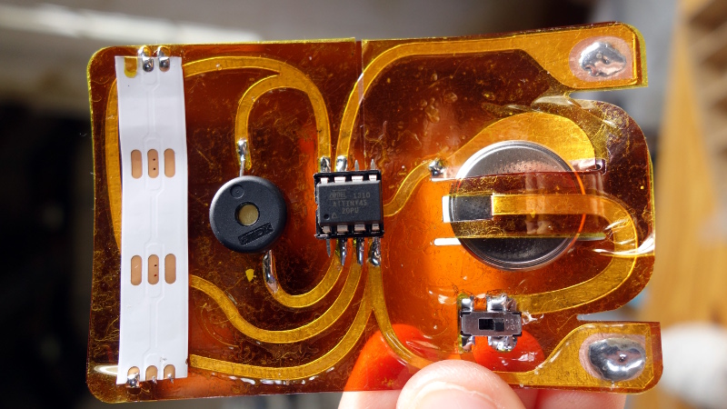
[Plusea] has come up with an entertaining interface for an ohmmeter, which instead of displaying the resistance on an LCD or a meter shows it as the colours of the code, via a set of addressable LEDs. The work is done by an ATtiny85 microcontroller, and the whole thing is mounted on a flexible PCB (fabrication of which is itself interesting, placing cut copper traces on a sheet of kapton and covering with a second kapton layer cut to be the solder mask). There is even a clever integration of a CR2032 battery holder from the PCB itself, though they admit that it could be made more compact with the use of SMD components instead of through-hole.
The write-up and associated photo album tells us a lot about the project, but is missing a crucial detail: a shot of it working. We’ll give them the benefit of the doubt on that front though, because we like the idea and its execution.
Strangely, this isn’t the first ohmmeter to use the resistor colour code in this way, we’ve previously brought you one featuring a light-up giant resistor.


Probably the most interesting detail for me is how they made the flex circuit board. Found more detail on another of their albums. https://www.flickr.com/photos/plusea/albums/72157684716598141
Even better, they have a tutorial :) http://www.kobakant.at/DIY/?p=5371
Interesting… kinda wanna make a smart watch as an arm band now… I’d probably flatten my DILs though and have them in holes.
How does an RGB LED do brown, black, and gray? I was thinking about the silver and gold… but no ohmmeter is going to be able to detect the tolerance anyway.
An RGB LED can do anything in it’s gamut. Same way a TV can show black, brown, and grey. Technically brown is just dark orange, more or less. Grey is just dim white. Black, admittedly, would benefit from a bit of dark plastic over the LEDs.
An ohmmeter *might* be able to measure tolerance. If you gave it the standard table of manufactured resistances, it could measure the actual resistance, compare it to the table, and decide how far off it is. It might turn out that a resistor marked 10% was actually 5% or less, so it could tell you something you didn’t know. Although AFAIK manufacturers test their resistors, and all the ones that fall within 5% are binned off as that, so 10% resistors are more or less guaranteed to be more than 5% off.
Might be that a resistor of one value, with a loose tolerance, is actually closer to a different value. So this would show up the wrong answer. I don’t suppose there’s anything in the code for that, presumably it’s just a table converting each digit to a colour.
Admittedly doing silver is going to be a bit tricky for an LED.
Try it before you act like it;s so easy.
First, there was a project shown here for a clock using resistor color codes. They had to completely replace certain colours like black, brown and grey to make it work at all. It is not nearly as simple as you think.
Second, if you showed a solid screen on your TV you’d have a very hard time recognizing brown from orange, orange from red or yellow, grey from white.
Third, human color vision doesn’t work the way you think it does. Google for the dress color optical illusion that swept the internet a few years ago.
Fourth, I tried building a color-based trivia buzzer system years ago using remote controls that were red, yellow, orange, green, blue, and violet. It was impossible to get the red, yellow, and orange sufficiently recognizable. I ended up using a character LCD to print the name of each color instead.
Also…as far as “tolerance”. That word doesn’t mean what you think it means.
While I agree with your other comments, what is he wrong about the tolerance? AFAIK that’s exactly how resistors are made and sold, they make a random distribution of resistors, measure them, bin them on their tolerance thresholds and then paint them. If that’s not the case, I’d like to know.
The word “tolerance” in this context means “permissible limit”. I understand what the OP said, but he is completely wrong on many levels.
Precision resistors have standard values that are much closer together than 5 or 10% resistors. 10.7 ohms is a 1% resistor you can buy. So if you measure 10.8 ohms, do we have a 10.7 ohm 1% resistor or a 10% resistor that is 10 or 12 ohms (bothl standard values of 10% resistor)? Perhaps it’s an 11 ohm 5% resistor?
Then also, remember we’re talking about permissible tolerance. Resistance varies directly with temperature. If that same 10.8 ohm measured resistor is really a 10% 12 ohm component, then when it gets hot, it can well rise above 13 ohms and still be within spec. If it were a 10.7 ohm 1% resistor, I would not expect nearly as much variability.
What you say about measuring and binning simply doesn’t make sense. The higher precision the component, the more standard values. 0.1% resistors are available and 10, 10.1, 10.2, 10.4, 10.5, 10.6, and 10.7 ohms are all standard values of 0.1% resistors. If your resistors are made of a material that has a stable resistance and you’re measuring and binning each one, then all resistors would 0.1% parts. Of course if you were actually measuring and binning all the resistors, they would also cost a hell of a lot more than they do, so that is just nonsense that the op made up and other people accept because it sort of makes sense.
Brown can be rendered in the same way as a television, a dark orange with more red than green balance, with tiny notes of blue. Grey is a lower than white constant RGB value (the same value per component). And black is OFF. No different to a pixel. :)
Orange always has more red than green. Proper orange I’d do with 100% red and 50% green. Or the same proportions scaled to whatever brightness.
Something I used to think about when people wrote HTML by hand (and better it was!). Actually most web pages now are hundreds of K of awful Javascript that must surely be machine-generate, or at least using huge third-party libraries. You couldn’t write code so awful and difficult to read. Perhaps they send it for a spin in the obfuscator first. It’s usually fine though when all you need to do, usually, is delete a couple of (P) elements (not gonna bother trying to do angle brackets here, though I know it IS possible). Then usually whatever advertising or signup or emotional blackmail nonsense that’s blocking the page can be removed, then you can get to the content.
Really greedy page owners will only send a small proportion of the page’s content anyway. It says “scroll down” but there’s really nothing there. The full page is only on the paid-for version.
Anyway… I wonder why adblockers can’t be a bit more clever and evade detection? How are they detected anyway? Could an adblocker, say, load up the ad image anyway but just not render it? I dunno. There must be methods round but if each site uses it’s own method of detection, that’s be difficult. Although not impossible, you’d just keep the per-site hacks on a database like the existing blacklist databases. I imagine though, again, that each site uses a library for adblock detection.
Anyway… beside that, I also had to figure out RGB trying to program games on the old Atari ST in STOS. That had 9-bit RGB, 3 bits for each. Or 12-bit for the STE. Then before THAT, the ZX Spectrum used RGBI, just 16 colours. But I figured out, blue was 1, red was 2, green was 4. It all adds up! So even that was educational at the age of 11 or so to figure out.
This post is slightly about colours. So as a whole it’s on topic!
BTW why am I always “awaiting moderation”? I posted hundreds of posts here for years, never used to get moderated.
Oh OK, not that one. Is it to do with size? And possibly the time taken between each post? Anti-spam measures?
See if this one gets it, for being too recent, three in a row!
^ It didn’t.
I know why I’m often “awaiting moderation”, because I sometimes post political incorrectness.
Speaking of political incorrectness – relevant to resistor color codes.
I’m sure everyone here recalls the memory mnemonic:
Bad Boys Rape Our Young Girls But Violet Gives Willingly.
Had to remember it for many exams.
Produce brown and gray is technically doable with Neopixels (and black is just turning the pixel off \o/ ); but reading the comments below makes me will to test it before I say anything.
All the components used there are SMD. There are no holes for pins in that flex PCB.
They’re using a DIP micro in a socket; a micro in a SMT package would be smaller.
I am not convinced this works. How would it work from a 3V source? The WS need more, I think below 4V the blue does not even turn on. And two CR2032 would be over the limit for the Attiny.
Quick and dirty way to make 2 batteries work with ATTiny: single diode to drop from 6v to about 5.3v which is below max operating voltage of 5.5
But I am not sure how blue LED worked with just 3v
I know from personal experience that WS2812Bs work fine on 3.7V, because I often power them directly from the output of a lipo cell. I’ve also had some success running them on 3.3V when necessary, but those cases are normally very few LEDs.
Am I missing something, or are there no pictures that show the circuit in action (i.e. with the LEDs lit)?
you aren’t missing anything.
Is there a reason why he used Kapton? Just lack of tools to etch a PCB? I can understand not wanting to spend and wait for one from mail-order if it’s just a one-off toy like this is. Not that toys aren’t useful, one can learn from making them just as much as something “serious”. I learnt a bit making an Arduino-based toy for a little kid who loved to press buttons (getting into trouble and his Mum having to hide the satellite TV remote). So I thought I’d make something with buttons specially for him.
I thought about going with IR remote cos it’d be easier to encapsulate and I wouldn’t have to leave a PCB with the tact buttons on it sticking out. But I couldn’t get the IR library to work so went with the buttons. Of course I would’ve covered the sharp bits (though he was 4, old enough to know not to poke his eye out).
Then eventually after a revelation (you can’t use pins 0 or 1 on an Arduino if you’re using the serial line for debugging etc!) I realised why the IR was giving such unreliable results.
Actually I think they should print something about that on the Arduino itself (admittedly the ones I have are knockoffs). Or at least, in big letters, on tutorial stuff. It’s the sort of thing you can overlook without thinking about it, since the Arduino environment abstracts away the dirty details of a lot of stuff, so I just treated serial.println as “magic” and let it do what it does, not my problem. Others surely must do the same! Don’t most people start with pin 0 when they’re using one?
This is me with years of programming experience, and a little with electronics, but no microcontrollers before.
Anyway, toys… I suppose Kapton is one way to go with using copper foil and a knife, though there’s no real point for it being flexible here.
I don’t see the purpose for this to be flexible… but I can imagine some projects where this would be particularly useful (maybe).
Seems like this is going to be lighter weight than most PCB boards, and I’ve got to admit the battery holder is pretty slick.
Looking at their other projects they make a lot of wearable circuits. One is a glove that measures resistance. It wouldn’t surprise me if they intended to integrate this into something like that. Even if not, I think the vinyl cutter to make low cost circuits from kapton and copper tape looks like a pretty nice way to prototype even if you don’t need it to be flexible.
From the intro of the write-up: “and the third a power-of-ten multiplier”
Someone’s used to 5% resistors :D
Greeeat idea!. Love the power of Neopixels as low-resolution displays.
This is a really cool project! I’m amazed at how many people actually have the color codes memorized! I never really bothered since I don’t use all that many different values of resistor, and I’m starting to get more into 0805 than through hole.
good project,the resistors are conflict to mesure