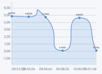
Coffee is the lifeblood of hackers, IT workers, and apparently, IT workers who are also hackers. [Omerfarukz] is clearly the latter. He works as part of a large team spread over multiple floors, all with coffee machines, any one of which is fair game. The problem is knowing which one has coffee that is ready to pour. He needed a non-invasive way to monitor the coffee machines.
 After contemplating a few solutions, he opted for one which wouldn’t offend the coffee gods. The machines use a high current to produce their heat, so he adapted some old remote control power sockets for the machines to plug into which would now monitor the current. A high current means the coffee is brewing and he knew that brewing takes one minute per cup, so the duration of the high current tells him the number of cups.
Having had no success with a current sensing transformer, he opted for an ACS712 chip, at heart a Hall effect sensor which outputs a voltage proportional to the test current. That goes to the IO pins of an ATtiny, and from there via serial to an ESP8266 and thence to Google Firebase for processing and notifying of IT workers in need of stimulation. For those wishing to partake, he’s posted the circuit on Github.
We’ve seen a few other non-invasive ways to do this monitoring. For example, there’s weighing the machines using a bathroom scale and the more manual phone-notifying alarm button.


The first civilian internet “thing” might have been a coffee pot … https://en.wikipedia.org/wiki/Trojan_Room_coffee_pot
Http error 418 …
https://developer.mozilla.org/en-US/docs/Web/HTTP/Status/418
We tea drinkers demand equal treatment!
“Coffee is the lifeblood of hackers, IT workers, and apparently, IT workers who are also hackers.”
IV drip.
Nice idea.
I think he could have omitted the attiny and fed the output from the current sensor directly to esp8266.
Has the ESP got analog pins? I think he’s using it as an ADC really.
The ESP8266 has a single analog input, with an input range of 0 – 1.0V. If you supply 3.3V, for example, you will damage the chip. Some boards like the NodeMCU have an on-board resistive voltage divider, to get an easier 0 – 3.3V range. You could also just use a trimpot as a voltage divider.
The ESPs ADC is no good here. A lot of noise…
is it just me or is his soldering horrible?
it’s not just you…
I am not a guy interested in electronics. I am a software developer. You can found a PCB diagrams on GitHub. All these things needs your helps. Ordered circuits from easyeda.com. Do not forget that, It is just a prototype not a final product.
I find myself asking, why not do the whole thing with the ESP8266? Why the AT tiny?
He says, Because ESP8266 does not have an analog input, but I wonder ….
It seems that the ADC input on the ESP8266 would do fine with a proper resistor divider,
and that may already exist on some boards.
Hi, You are correct. I am not an electronics expert, I am a software developer.
Tried many variations like a voltage divider. ESP-01 have not an analog input pin but other boards with expressif chips like an ESP-12E have. PCB design mentioned on GitHub based on ESP-12E. The project is just begun. I am currently working on ESP-12E. You can access the current design on easyeada.com with the following link. I need your valuable comments and contributions.
https://easyeda.com/editor#id=|46d8fcc49f454f118ce3ada76eff47c3|711a99ffcc884424a54e9966cd12c8d1|c213e35520664656ba5db52fb86023f0|988cb5c2197340a280405cadef13b3b0|749c8c31eb7f4958a870b642658cd2bd|8f19b2b598a7407dbb315bfb04e5a5c0|75c625af8f62484b8a3e7860b1802ac6
I need to experiment with the ADC input on the ESP8266 — my use case is a outdoor temperature monitor that runs off a battery. I want to monitor the battery voltage and have it send me a notification when I need to swap in a new battery. If I can be any help, let me know — I am a software guy who has been sucked into the black hole of electronics. But almost no electronics is needed for this tweak.
The ESPs ADC does not have separate reference supply or ground. The 300ma drawn in transmission produces a huge amount of noise. Perhaps I’d you ate measuring some slow changing value and you can read between transmissions it may be useful, but for fast regular samples it is better to us an external ADC. And ad microcontroller are often cheaper than a dedicated ADC, micros offer a better option.
I built something similar using https://learn.openenergymonitor.org/electricity-monitoring/ct-sensors/introduction with a 1V/30A style CT and an esp8266. The CT worked well for me, and it seems like it might provide greater safety margins.
SCT sensors are easy to use and I bought and tried two of them but as I described on medium, I don’t like to have additional wires. The final solution with ACS712 is simple as I supposed: Plug a device between power source and device. That’s all you have to.