You don’t usually think of simulating Verilog code — usually for an FPGA — as a visual process. You write a test script colloquially known as a test bench and run your simulation. You might get some printed information or you might get a graphical result by dumping a waveform, but you don’t usually see the circuit. A new site combines Yosys and a Javascript-based logic simulator to let you visualize and simulate Verilog in your browser. It is a work in progress on GitHub, so you might find a few hiccups like we did, but it is still an impressive piece of work.
If you aren’t up on Verilog, you can use the “Load Example Code” button to pick a few samples. You might try this if you want something really simple:
module test(
input a,
output b
);

assign b=~a;

endmodule
That creates a circuit like this:
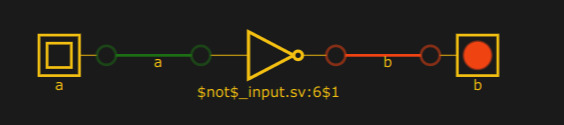
The A button is live, so clicking it will change the little faux LED to red along with the associated wires. It may not be obvious, but you can drag components around to suit you. You can also delete wires and create new connections. If there is a way to add and delete components, we couldn’t figure it out.
This isn’t a bad way to learn Verilog since you can quickly see what the code is doing. It isn’t flexible enough to be a workhorse simulator, though. For example, naming something clk puts a clock input on the schematic, but using any other name as a clock leaves it as a button like “a” in the example above. There’s no way to set the clock either.
This is fun, though. Yosys has a lot of features we usually don’t use, including the ability to generate graphviz files with schematics of the design, although they aren’t as clear as this. We’d love to see this married with Falstad as the simulation engine so you could basically use Verilog modules as part of your simulation. That simulator can do digital circuits, it just doesn’t accept Verilog. If you want real simulation in your browser, try EDA Playground, which we use a lot.


Now if we could make a logic diagram and output Verilog…
Like this can? https://github.com/reds-heig/logisim-evolution
I’ve always stuck with the old Xilinx 95xx series CPLDs, cause first, I have drawers full of ’em, and second, I only design using the schematic tool… It’s way easier for me to define logic visually by schematic than trying to work out lines of code. My brain just prefers visual logic, I guess. This is pretty cool!
This has been possible for years in Altera Quartus; still nice to see the magic of the synthesizer
And here I thought Giorgio Moroder was the one who showed us the magic of the synthesizer…
Wait, are you forgetting Vangelis ?…
What about Dick Hyman (“The Minotaur”) and Walter/Wendy Carlos?
OK, now, let’s have a VHDL version :-)
Maybe using the GHDL frontend ? :-D
YoSys can use vhdl2verilog although I would expect some of the translation is wonky — I haven’t tried it in a long time.
Very cool, this is like logisim but not done the wrong way around.
Logisim (and also hneemann’s Digital) have the ability to integrate Verilog and VHDL defined components in your circuit.
This would be super cool integrated into IceStudio, the block based IDE for IceStorm.
The author here. Thanks for posting this on Hackaday and for all the useful feedback!
I designed the tool to be used for a university course, for teaching digital design simultaneously with Verilog coding for computer science students. The focus is on synthesis and schematic readability, because I want my students to understand that they are building circuits, and not writing software.
The project is open source and contributions are most welcome. I will encourage my students to enhance the simulator with features it needs. And I’d like to have a lot: adding/removing components by hand, saving and loading, export to SVG, export to Verilog, clock control, memory state editing, waveform inspection, and so on.
Hmmm, is it me, or is R and S always the wrong way around in the simulator?
I was trying to run a code which involved the the delays, did’nt work then I tried to load the existing example code for D flip flop to check how clock and timing is managed that didnt work too. Anyone help please if it working for you.
There’s something similar available in Logisim and Digital. Adding a component which is defined by Verilog or VHDL and integrating it with the rest of the circuit. Super-Cool for visually seeing your Design in action when you actually don’t have a FPGA at Hand.