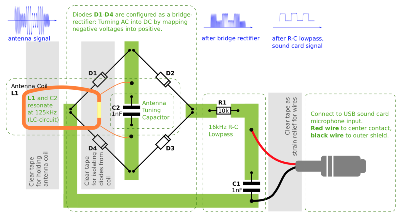
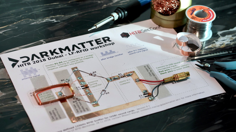
We feature plenty of printed projects here on Hackaday, though they tend to be of the three dimensional type thanks to the proliferation of affordable 3D printers. But in this case, [Milosch Meriac] has managed to put together a printable design that’s not only a very cool hack, but is made up of a scant two dimensions. His creation, which could perhaps be considered something of an interactive circuit diagram, allows anyone with a paper printer and a few passive components to make a functional low-frequency RFID sniffer.
 [Milosch] tells us the goal of the project is to lower the barrier for experimenting with the RFID technology that’s increasingly part of our everyday lives. Rather than having to use something expensive and complicated such as an oscilloscope, experimenters can simply plug their DIY RFID sniffer into their computer’s line-in jack and explore the produced waveform with open source tools.
To create a paper RFID sniffer, you start by printing the image out on a thick piece of paper, like card stock. You then apply foil tape where indicated to serve as traces in this makeshift PCB, and start soldering on the components as described in the text. [Milosch] says the assembly procedure is so simple even a kid can do it, and the total cost of each assembled sniffer is literally pennies; making this an excellent project for schools or really any large group.
If you want to play it safe the sniffer can be connected to a USB sound card rather than your machine’s primary sound hardware, and still come in dirt cheap. [Milosch] stops short of explaining the software side of things in this particular project, but any tool which can use input from the sound card as a makeshift oscilloscope should be a good start.
In the past we’ve seen [Milosch] perform low frequency RFID sniffing through the sound card with the powerful baudline tool, but if you want a little more capable hardware, we can point you in the right direction.


Just a simple detector.
You mean, you could do it with a NE555? :)
Add a dc offset of half the amplidude. Send the positive peak of the wave to the left channel, invert the negitive and send it to the right channel. Double the frequency you are able to sample.
Very similar to how I got started with electronics – those Dick Smith kits with a grid where you wired your circuit point-to-point. Ahhh, those were the days (when you could actually see the components!).
was it the little plastic board with the screws of the one with the springs?
The screw ones were prety cool but the spring ones made life so much simpler until the springs lost their tension then you were forever trying to find the open circuit.
I had another… started with a paper grid (with circuit drawn on it) that was stuck to chipboard. Screws were a pain to get in because I didn’t have a drill to drill pilot holes! I then moved to something called a “P-box” which was like a veroboard with no copper strips, just holes and the wires connected underneath. Finally I got one of those spring-clip “101 in 1” “kits”, which worked really well until the springs got tarnished and gave intermittent connections.
I wanted the Dick Smith kits but my family moved to a remote part of world where I had no hope of buying one. I did, however, get my hands on an old electronics textbook and I was able to buy a handful of discrete components which I then wired up with some 240V terminal blocks. First time I wired up an oscillator and hooked up the speaker I damn near wet myself!
I like the idea, please offer kits on eBay, 10 pack would be good :-)
You should check into chibitronics:
https://chibitronics.com/
so .. you sandwich this in between the reader and the rfid tag ?
That’s pretty cool I have an 80m DIrect conversion DSB receiver using that technique of copper tape. It’s works great.
Just pop down a bit of electrIcal tape over a track if you need to cross traces
This would be a good intro for my students.
Can anyone recommend simple software to view the waveforms? Windows or Linux preferred.
Here’s a list of various software that might do the job
https://www.dxzone.com/catalog/Software/Oscilloscope/
It looks like there are some useful tools there, thank you for the link!
Hi – I have some Zener diodes (5.1V, 1W) and Germanium diodes (1N34A, Forward voltage drop 1V @ 5mA). I also have one KIA 7805P three-terminal positive voltage regulator (http://www.kec.co.kr/data/databook/pdf/KIA/Eng/KIA7805AP~KIA7824AP.pdf).
Would any of these components suffice for the Schottky diodes? Thank you in advance.
It would be interesting if the headphone output could be used to create a carrier, and thus make a full analog RFID reader.
Would be interesting if the Circuit could be modified to Actually do that.
So, without the components, you have nothing. If you have the components, but not the piece of paper, you can still make the device. So really, it’s a circuit, made out of components. The paper doesn’t even connect anything together, the foil does that. Literally any non-conducting solid object could replace the paper. The paper is the single least important component. I feel this article is titled misleadingly.