If we say that a hacker is somebody who looks at a “solved” problem and can still come up with multiple alternative solutions, then [Charles Ouweland] absolutely meets the grade. Not that we needed more evidence of his hacker cred given what we’ve seen from him before, but he recently wrote in to tell us about an interesting bit of problem solving which we think is a perfect example of the principle. He wanted to drive a salvaged seven segment LED display with an AVR microcontroller, but there was only one problem: the display needs 15V but the AVR is only capable of 5V. So what to do?
 As it turns out, the first step to solving the problem was verifying there was actually a problem to begin with. [Charles] did some experimentation and found that the display didn’t actually need 15V to operate, and in fact would light up well enough at just 6.5V. This lowered the bar quite a bit, but it was still too high to power directly from the chip.
There were a few common ways to solve this problem, which no doubt the Hackaday reader is well aware of. But [Charles] wanted to take the path less traveled. More specifically, the path with the least amount of additional components he had to put on his PCB. He set out to find the absolute easiest way to make his 5V AVR light up a 6.5V LED, and ended up coming with a very clever solution that some may not even know is possible.
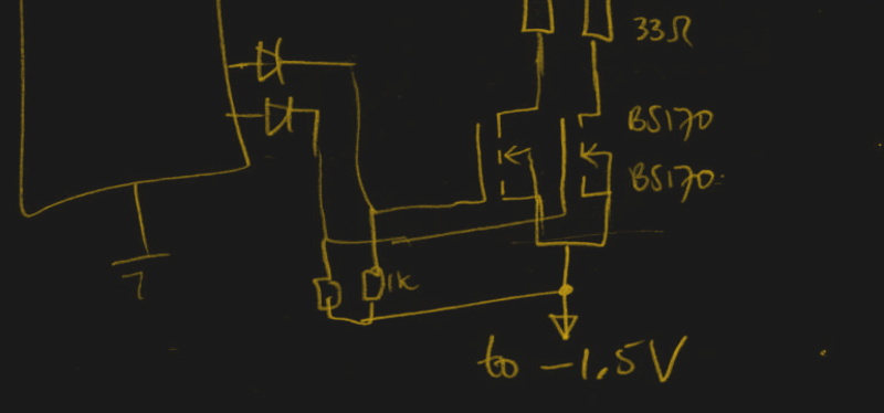
He reasoned that if he connected the source pins of two BS170 MOSFETs to a voltage of -1.5V, even when the AVR pin was 0V, they would be still be receiving 1.5V. This virtual “step ladder” meant that once the AVR’s pin goes high (5V), the relative voltage would actually be 6.5V and enough to drive his LEDs. Of course the only problem with that is that you need to have a source for -1.5V.
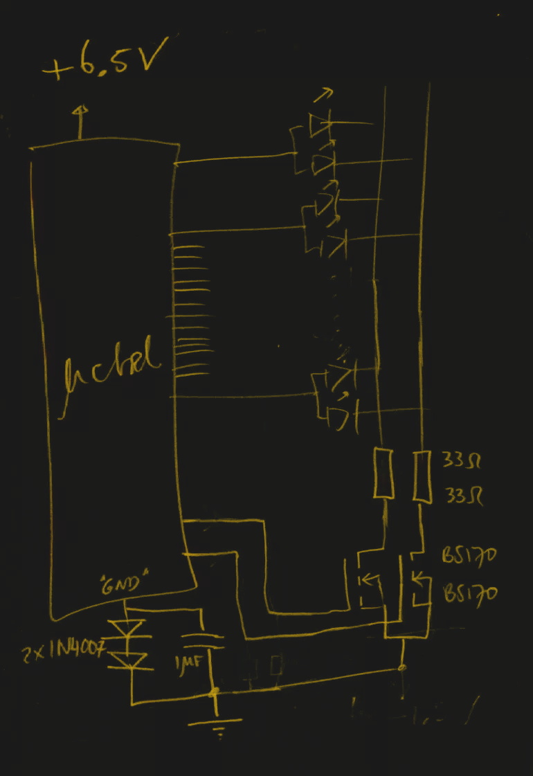
Getting a negative voltage would normally require adding more components to the design (which he set out to avoid in the first place), but then he came up with another clever idea. To pull the trick off, he actually feeds the AVR 6.5V, but raises the ground voltage by 1.5V with the addition of two 1N4007 diodes. This way the AVR gets a voltage within its capabilities and still can provide a relative 6.5V to the LEDs.
One might say [Charles] took the Kobayashi Maru approach, and simply redefined the rules of the game. But such is the power of the confounding negative voltage.


Adding three diodes between micros ground pin and 0V would solve the problem.
Isn’t that what they did?
But, isn’t that exactly what he did… and with only two diodes?
lol found the tl;dr
I did something similar with non rail to rail opamps powered by a single battery. It would clip when the signal went near 0V, couple of diodes solved the problem :)
Mattel Electronics used the same design to get negative rail in their 1979 Intellivision systems. 3 diodes to get about -3.3v; https://console5.com/wiki/Intellivision#/media/File%3ASylvania-Intellivision-Power-Supply-Schematic.png
It could also be done running the microcontroller without shifting the ground side. Sometime you want to connect it to external devices and that required a 0V ground rail e.g. TTL serial, USB. etc
Usually the NMOS transistors are a bit stronger (i.e. less voltage drop), so one would use it for driving a load (LED negative pin) at logic ‘0’. A voltage divider can be used to level shift for controlling a coupe of PNP on the shared positive rail.
Regardless of the approach, you do run the chance of letting the smoke out of the micro if/should your LED leaks current when off/shorted. Without the forward drop, the I/O pin sees the full voltage of the other rail which is outside of the max voltage specs. I have replaced LED lighting to know that they can fail shorted.
Why’d he need to go through all the trouble of creating a negative voltage, when he could have put the diodes on the positive supply side of the MCU and simply pulled the LEDs low.
The 1.5 Volts left over would not exceed the LEDs threshold voltage and no current would flow. Putting the pin in Hi-Z state would further reduce the leftover voltage to about 0.8 Volts because you’d have to pass the chip’s input protection diode.
The AVR can sink more current than source anyways, so it would be less stressing to the component.
It seems the diodes are connected as 2 sets of 15 in common-kathode configuration inside the display, so you can’t do that. Otherwise, he wouldn’t have had to switch both the high-side and low-side anyway.
This only works if the MOSFETs gate threshold is larger than 1.5V; the datasheet for the BS170 says 0.8V minimum, 2V typical, 3V maximum, and this gate threshold drops with increasing temperature. It is possible some would conduct at 1.5V, a series diode with a resistor to ground would solve that.
I was thinking of using a capacitor and a couple diodes to make a charge pump for each high-side output, but that still requires some 45 extra parts for 15 channels (or 30 if you can use SMD double diodes).
The threshold is defined as the limit where 100µA of current can flow between source and drain. The MOSFET is basically a voltage controlled resistor.
In this application it doesn’t matter if some current flows, as long as it’s small enough that the LEDs don’t visibly light up.
And how much do you think is necessary for it to be visible. I did some tests about a year ago, and 1 million times less current than the common 20mA: 20nA is too little, you can’t see that. But 50nA is visible (in the dark). 50 uA is what I target for the leds that I sell as indicator leds.
About 1 mA is usually just visible for regular indicator LEDs. If you’ve got diffusing colored lenses, you won’t see anything in the microamp range because the casing absorbs too much of the light.
This depends greatly on how you define “regular indicator LEDs”. I’ve used LEDs that I would call regular and for indication purposes, and you can see a glow at 100uA easily normally, and at 20uA in the dark. This was with coloured diffusing lenses.
I’m taking about normal cheap diffused 5mm indicator LEDs.
http://i.ebayimg.com/images/g/1T0AAOxyM89SblOi/s-l300.jpg
These aren’t particularly sensitive to current, nor very bright. They are indicator lights designed for the purpose of being a glowing dot on a device to indicate function. People nowadays mix these with the “superbright” LEDs, which are those with lighter tinted lenses that actually project a beam of light, which is really annoying when manufacturers put them in products and they light up the entire room at night.
Also notice that LED light output is more or less proportional to the current going through (except for very high currents)
So dropping the current from 20 mA to 20 µA causes a contrast change of about 1000:1 give or take. The contrast ratio of a white paper and a line drawn in black marker under ordinary room lighting is about 150:1. Going from 20 mA to 100 µA is a contrast ratio of 200:1 which is more than enough to make the LED appear completely off under normal circumstances, especially if you put a diffuser in front of it.
I’ve seen an FPGA inside an oscilloscope where they fed almost -5V through resistors into two I/O pins.
According to the IBIS data the resulting current is barely acceptable.
Does anyone have an idea why they did that? Is it to counter ground bounce?
Were those I/O pins being used for anything? Maybe there was some instability on the I/O rail that was cleaned up by feeding current through the TVSes.
1 μF capacitor placed that way means the microcontroller gets short pulse of 6.5 V when the voltage is applied. Better solution would be to place it “conventionally” between VCC and GND pins.
I think the solution found is not a good way to do things. Use a P-FET or PNP transistor to switch the high side and drive the other side with the arduino or something like that. You may need to add an about-3V voltage drop component (say a zener or a led) in the base or gate circuit. That way things will work reliably. The “1.5V seems enough, and doesn’t turn on the fet” is “outside spec” and may not work next time around. Good enough to make it work on saturday night, but not good enough for production.
Valid point. According to the datasheet the threshold voltage VGS(TH) is between 0.8V and 3.0V. Unfortunately, the datasheet of the BS170 contains no transfer characteristics graph to check what happens at 1.4V. Had I used the 2N7000, Philips provides a transfer characteristic graph of that one. Fig. 6 in the datasheet shows that drain current is still near zero at 1.4V.
I though of adding diodes in the gate lines to overcome this potential problem, as you can see in the illustration that is in the header of this Hackaday article. But then again, that would increase the MOSFET’s resistance at ON state.
That can kill the micro. Atmega32 works at 5v5* max. And IO pins can handle Vdd+.5V. When you switch on a high side transistor, and don’t drive low some of the LEDs, the micro can potentially get the full 6v5 and die with a smoke.
* The datasheet says abs. max. 6v. Also, the LEDs probably do not conduct under 1V, so theoretically there’s plenty of headroom. I still wouldn’t rely on that clock.
Does this mean that, theoretically, if the power supply was 120V DC, and I used a shitload of diodes to drop most of that for the AVR, I could use the AVR to switch that high a voltage? By switching between “1” and “Z” states? There’s just something here that doesn’t sit right. I can see it makes sense but it doesn’t quite click.
It would switch the output between 115 (off) and 120 (on) Volts. Or anything else, depending on the voltage stability of your diodes.
No, that would be 1 and 0, surely? High-Z is no current flow.
Is High-Z really High-Z beyond uC’s supply voltage?
High-Z is no current flow only under the assumption that the voltage at the output pin is within certain limits. At “Z” state the voltage at the output will settle at 115V, maybe 114V. If the voltage goes any lower than that, the body diode inside the AVR will start to conduct and if the resulting current is strong enough, it will kill the AVR.
Placing diodes on the power rail of a micro is a silly idea. temp & load will constantly fluctuate the power rail.
all he had to do was put a series 0.1uf cap on the output pin, a series diode then another 2.2uf cap to ground along with a parallel say 500k resistor to gnd. PWM the output and it would charge the 2.2uf cap. the 0.1uf would isolate the pin from the gate so no matter high or low the fet would do nothing unless the output toggled fast enough to charge the cap, hence driving the gate.
Can you draw up a quick schematic? This sounds like a really neat idea but I’m having a hard time understanding your description.
The circuit refered to is known as a “charge pump” and it needs 2 diodes and 2 caps to boost the voltage.
And it is useless in this particular case because the higher voltage is needed on a lot of output pins. Look at the short wire stubs in the 2nd schematic. These probably go to the anodes of a lot of diodes from a display matrix.
In this case it also does not matter if the voltage over “lift diodes” fluctuates. It can be anything between 400mV and 700mV and the circuit will still work. A lot of microcontrollors are also comfortable with fluctuating power supply voltages. A lot of 5V uC’s can be used from anything between 5V5 or 6V0 down to 2V or sometimes even less.
Wouldn’t the AVR be endangered by a 6.5V to gnd voltage at the moment of turning it on, before everything stabilises to give a 6.5V-1.5V=5V situation?
Yes, this is a valid concern.
Especially because of the 1uF over the diodes.
This cap has to be charged through the uC, which takes time.
It would have been much better if this 1uF was connected as an extra buffer cap directly over the uC power supply pins like a regular decoupling capacitor. In that case it slows down the rate in which the voltage over the uC power pins rises.
To solve complicated mosfet-amplifier calculations with positive and negative voltages,
elevate the most negative voltage to 0V and all others accordingly.
everything is relative if nothing else is connected.
Did the same to drive WS2811/2812 LEDs directly with an ESP8266. Check it out at: https://www.youtube.com/watch?v=letCT3vq8V4
Another great example of the same principle. Love it how you reduce 5V to 3.7V and level shift at the same time by using a diode in both the GND line and the VCC line!
And from the title I was expecting that someone figured out how to circuit-bend the micro through it’s I/O or power pins to apply a negative body voltage and thereby improve performance. Oh well.
This trick is also usefull if you want to switch some power MOSfets, and the only fet’s you have available Need a little too much voltage on the gate to switch reliably at 5V.
But when you do something like this, carefully place your decoupling caps.
In the hand drawn schematic above there is a 1uF cap over the diodes. Don’t know what that is doing there, but the decoupling caps should always be as close to the uC as possible and directly tied to the uC pins, not to the power supply.
So in this case they go from +6V5 to the Anode of the top led, and GND pin of the uC. Not to the “GND” reference of the rest of the circuit.
A good point (also made above by Vojt’ák and name) and thanks for your comments. Indeed, if that cap is the only cap, there would be a problem during switch on, because it takes time for the cap to charge and during that time the voltage over the microcontroller could reach up to 6.5V. I guess I wasn’t thinking. Thankfully in the final diagram there is also a 1uF cap directly over the microcontroller’s pins and that eliminates the problem.