Adding Temperature Sensor Functionality To The CH32V003 MCU

As cheap as the WCH CH32V003 MCU is, its approximately $0.10 price tag looks far less attractive when you need to start adding on external ICs for missing basic features, such as temperature measurement. This is a feature that’s commonly found on even basic STM32 MCUs. Fear not though, as [eeucalyptus] shows, you can improvise a working solution by finding alternative sources that can act as a thermometer.

Plot of the temperature measurement using the improvised CH32V003 -based temperature sensor. (Credit: eeucalyptus)

The CH32V003 is a low-end, 32-bit RISC-V-based MCU by the China-based Nanjing Qinheng Microelectronics, commonly known abbreviated as ‘WCH’, and featured on Hackaday previously. Although it features a single-core, 48 MHz CPU, its selection of peripherals is fairly basic:

So how do you create an internal temperature sensor using just this? [eeucalyptus] figured that all that’s needed is to measure the drift between two internal clocks – such as the LSI and HSI – as temperatures change and use this to calibrate a temperature graph.

Unfortunately, the LSI isn’t readily accessible, even through the Timer peripheral. This left the AWU (automatic wake-up unit) which also uses the LSI as a clock source. By letting it go to sleep and wake up after N LSI cycles, the AWU enabled indirect access to the LSI.

Internal diagram of the CH32V003 MCU. (Credit: WCH)

After calibrating against room temperature (~22 °C) and ice water (0 °C), a temperature plot was obtained, which could conceivably be somewhat accurate. As [eeucalyptus] warns, this is a kind of calibration that likely differs per MCU, and no attempt to quantify the absolute accuracy of this method has been made yet. Even so, as a crude temperature measurement, it might just be good enough.

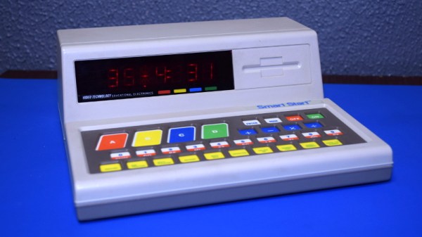
Teardown: VTech Smart Start

Regular readers may be aware that I have a certain affinity for vintage VTech educational toys, especially ones that attempted to visually or even functionally tie in with contemporary computer design. In the late 1980s, when it became obvious the personal computer was here to stay, these devices were seen as an affordable way to give kids and even young teens hands-on time with something that at least somewhat resembled the far more expensive machines their parents were using.

Much Smarter: VTech PreComputer 1000

A perfect example is the PreComputer 1000, released in 1988. Featuring a full QWERTY keyboard and the ability to run BASIC programs, it truly blurred the line between toy and computer. In fact from a technical standpoint it wasn’t far removed from early desktop computers, as it was powered by the same Zilog Z80 CPU found in the TRS-80 Model I.

By comparison, the Smart Start has more in common with a desktop electronic calculator. Even though it was released just two years prior to the PreComputer 1000, you can tell at a glance that it’s a far more simplistic device. That’s due at least in part to the fact that it was aimed at a younger audience, but surely the rapid advancement of computer technology at the time also played a part. Somewhat ironically, VTech did still at least attempt to make the Smart Start look like a desktop computer, complete with the faux disk drive on the front panel.

Of course, looks can be deceiving. While the Smart Start looks decidedly juvenile on the outside, that doesn’t mean there aren’t a few surprising technical discoveries lurking under its beige plastic exterior. There’s only one way to find out.

Continue reading “Teardown: VTech Smart Start”

Open-Source Thermostat Won’t Anger Your Landlord

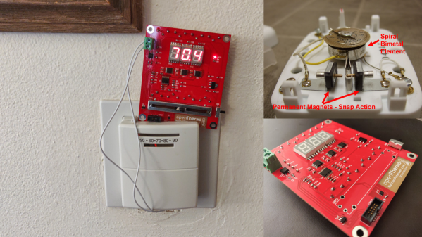
[Nathan Petersen] built a Hackable Open-Source Thermostat to smooth out temperature fluctuations caused by the large hysteresis of the bimetallic strip thermostat in his apartment. While it may be tempting to adjust the “anticipator” to take care of the problem or even replace the bimetallic thermostat with an electronic version, building your own thermostat from scratch is a good way to add to your project portfolio while making your way through college. Plus, he got to hone his hardware and software design chops.

The hardware is designed around the STM32, using a cheap, minimal variant since the device just needs to sense temperature and control the furnace in on-off mode. The TMP117 high-accuracy, low-power, temperature sensor was selected for temperature measurement since accuracy was an essential feature of the project. Dry-contact output for the furnace is via a normally-open solid state relay (opto-isolator). For the user interface, instead of going the easy-route and using an I2C/SPI OLED or LCD display, [Nathan] used three 7-segment LED displays, each driven by an 8-channel constant current driver. The advantage is that the display can be viewed from across the room, and it’s brightness adjusted via PWM. Temperature set-point adjustment is via a simple slide potentiometer, whose analog voltage is read by the micro-controller ADC. To remind about battery replacement, a second ADC channel on the micro-controller monitors the battery voltage via a voltage divider. The PCB components are mostly surface mount, but the packages selected are easy enough to hand solder.

[Nathan]’s Github repo provides the hardware and firmware source files. The board is designed in Altium, but folks using KiCad can use either the awesome Altium2KiCad converter or the online service for conversion. (The results, with some minor errors that can be easily fixed, are quite usable.) Serendipitously, his PCB layout worked like a charm the first time around, without requiring any rework or bodge wires.

The firmware is a few hundred lines of custom bare-metal C code, consisting of drivers to interface with the hardware peripherals, a UI section to handle the user interface, and the control section with the algorithm for running the furnace. [Nathan] walks us through his code, digging into some control theory and filtering basics. After making a few code tweaks and running the thermostat for some time, [Nathan] concludes that it is able to achieve +0.1°F / -0.5°F temperature regulation with furnace cycles lasting about 10-15 minutes (i.e. 4-6 cycles per hour). Obviously, his well insulated apartment and a decent furnace are also major contributing factors. Moving on, for the next version, [Nathan] wants to add data collection capabilities by adding some memory and SD card storage, and use an RTC to allow seasonal adjustments or time-based set-points.

This is his first attempt at a “functional’ useful project, but he does love to build the occasional toy, such as this POV Top.

Speeding Up Drawing To MCU-Connected Serial Displays

Writing image data to serially connected (SPI/I2C) displays from a microcontroller is easy enough these days, courtesy of standards defined by the MIPI Alliance, yet there are some gotchas in it which may catch someone using it unaware. [Larry Bank] wrote up a good summary of how one can get maximum performance out of such a display link.

At the core is the distinction between pixel data and command transmissions. The change from command to pixel data mode requires signaling, which takes precious clock cycles away from transferring pixel data between the MCU and display. The common MIPI DCS instruction set allows for a big reduction in needed data transfers by allowing parts of the display to be addressed instead of requiring a full refresh. Yet by not properly segmenting command and data transfers, one ends up unnecessarily slowing down the process.

The result is that one can run something like a Pac-Man emulator on an AVR MCU with a sluggish 320×480 SPI LCD at 60 FPS, as one can see in the video that is embedded after the break. Check the article for another demo video as well.

Continue reading “Speeding Up Drawing To MCU-Connected Serial Displays”

The Clementine Spacecraft

Preventing Embedded Fails With Watchdogs

Watchdog timers are an often overlooked feature of microcontrollers. They function as failsafes to reset the device in case of a software failure. If your code somehow ends up in an infinite loop, the watchdog will trigger. This is a necessity for safety critical devices. If the firmware in a pacemaker or a aircraft’s avionics system gets stuck, it isn’t going to end well.

In this oldie-but-goodie, [Jack Ganssle] provides us with a great write up on watchdog timers. This tells the story of a failed Clementine spacecraft mission that could have been saved by a watchdog, and elaborates on the design and implementation of watchdog techniques.

If you’re designing a device that needs to be able to handle unexpected failures, this article is definitely worth a read. [Jack] explains a lot of traps of using these devices, including why internal watchdogs can’t always be trusted and what features make for a great watchdog.

Thanks to [Jan] for the tip!

“DB” = Abbreviated Microcontroller Debugging

We’ve all been there. When debugging a microcontroller project, we just want to put in a print statement to figure out what’s going on with the microcontroller in real time. However, advanced embedded programmers know that printf statements are verboten: they’re just too SLOW. While not fixing this plight entirely, [Atakan Sarioglu] has come up with a clever way to create readable debug messages with minimal runtime overhead.

[Atakan Sarioglu]’s innovation, called BigBug (Github), is a dynamically-generated codebook. The codebook translates abbreviated messages sent over serial (UART here) to longer-form human-readable messages. To generate the codebook, BigBug automatically parses your comments to create a lookup between an abbreviation and the long-form message. When you are running your program on the microcontroller, BigBug will translate the short codes to long messages in real-time as you send log/debug data over serial. Continue reading ““DB” = Abbreviated Microcontroller Debugging”

Negative Voltage Pushes AVR To New Heights

If we say that a hacker is somebody who looks at a “solved” problem and can still come up with multiple alternative solutions, then [Charles Ouweland] absolutely meets the grade. Not that we needed more evidence of his hacker cred given what we’ve seen from him before, but he recently wrote in to tell us about an interesting bit of problem solving which we think is a perfect example of the principle. He wanted to drive a salvaged seven segment LED display with an AVR microcontroller, but there was only one problem: the display needs 15V but the AVR is only capable of 5V. So what to do?

As it turns out, the first step to solving the problem was verifying there was actually a problem to begin with. [Charles] did some experimentation and found that the display didn’t actually need 15V to operate, and in fact would light up well enough at just 6.5V. This lowered the bar quite a bit, but it was still too high to power directly from the chip.

There were a few common ways to solve this problem, which no doubt the Hackaday reader is well aware of. But [Charles] wanted to take the path less traveled. More specifically, the path with the least amount of additional components he had to put on his PCB. He set out to find the absolute easiest way to make his 5V AVR light up a 6.5V LED, and ended up coming with a very clever solution that some may not even know is possible.

He reasoned that if he connected the source pins of two BS170 MOSFETs to a voltage of -1.5V, even when the AVR pin was 0V, they would be still be receiving 1.5V. This virtual “step ladder” meant that once the AVR’s pin goes high (5V), the relative voltage would actually be 6.5V and enough to drive his LEDs. Of course the only problem with that is that you need to have a source for -1.5V.

Getting a negative voltage would normally require adding more components to the design (which he set out to avoid in the first place), but then he came up with another clever idea. To pull the trick off, he actually feeds the AVR 6.5V, but raises the ground voltage by 1.5V with the addition of two 1N4007 diodes. This way the AVR gets a voltage within its capabilities and still can provide a relative 6.5V to the LEDs.

One might say [Charles] took the Kobayashi Maru approach, and simply redefined the rules of the game. But such is the power of the confounding negative voltage.