Furby Plus Borges Equals Borgy

What do you get if you cross a Furby with a master of 20th Century literature? The Borgy. Argentinian hacker [Roni Bandini] found an old Furby and decided to hack it by altering its personality. His inspiration was the Argentinian writer Jorge Louis Borges, one of the pioneers of surrealist writing. The idea is that, at random times during the day, the Borgy will share a bit of wisdom from Borges to inspire and enlighten.

[Roni] hacked the Furby to replace the speaker with a more powerful one, and built a base to hold the larger speaker and a switch which can activate Borgy. He also used an Arduino Nano and a Sparkfun MP3 player shield loaded with the samples of Borges.

When the Furby speaks, it shares some wisdom from Borges. It’s a simple, but a surprisingly effective hack that could be very useful for someone seeking inspiration.  Or, as Borges himself once said: “Don’t talk unless you can improve the silence.”

Continue reading “Furby Plus Borges Equals Borgy”

An Over-engineered LED Sign Board

Never underestimate the ability of makers in over thinking and over-engineering the simplest of problems and demonstrating human ingenuity. The RGB LED sign made by [Hans and team] over at the [Hackheim hackerspace] in Trondheim is a testament to this fact.

As you would expect, the WS2812 RGB LEDs illuminate the sign. In this particular construction, an individual strip is responsible for each character. Powered by an ESP32 running FreeRTOS, the sign communicates using MQTT and each letter gets a copy of the 6 x 20 framebuffer which represents the color pattern that is expected to be displayed. A task on the ESP32 calculates the color value to be displayed by each LED.

The real question is, how to calibrate the distributed strings of LEDs such that LEDs on adjacent letters of the sign display an extrapolated value? The answer is to use OpenCV to create a map of the LEDs from their two-dimensional layout to a lookup table. The Python script sends a command to illuminate a single LED and the captured image with OpenCV records the position of the signal. This is repeated for all LEDs to generate a map that is used in the ESP32 firmware. How cool is that?

And if you are wondering about the code, it is up on [Github], and we would love to see someone take this up a level. The calibration code, as well as the Remote Client and ESP32 codes, are all there for your hacking pleasure.

Its been a while since we have seen OpenCV in action like with the Motion Tracking Turret and Face Recognition. The possibilities seem endless. Continue reading “An Over-engineered LED Sign Board”

Advent Calendar – ‘Tis The CNSeason

CNC machines are powerful tools when used correctly, but it’s often necessary to test a new machine before getting into serious production work. This advent calendar is a great festive project that was designed to put a CNC through its paces.

The calendar is made primarily from wood. This is an excellent choice for test machining projects, as it is softer and less likely to cause tool or machine damage when compared to steel or aluminum. The calendar base was first milled out using end mills, while a 30-degree V-bit was used to engrave the days of the week. Brass brazing rod was then used to create hangers for the calendar tags.

Thanks to the clever use of chalkboard paint and removable tags, the calendar can be reconfigured to work for any given year and month combination — just in case you wish to have an advent calendar year round. Overall, it’s a good low-intensity machining project that would also be a fun craft project for kids.

As it’s that time of year, you might like this blinky advent calendar, too. Video after the break.

[Thanks to Michael for the tip!]

Continue reading “Advent Calendar – ‘Tis The CNSeason”

Crystal Oscillators Explained

We’ve read a lot about oscillators, but crystal oscillators seem to be a bit of a mystery. Hobby-level books tend to say, build a circuit like this and then mess with it until it oscillates. Engineering texts tend to go on about loop gains but aren’t very clear about practice. A [circuit digest] post that continues a series on oscillators has a good, practical treatment of the subject.

Crystals are made to have a natural resonant frequency and will oscillate at that frequency or a multiple thereof with the proper excitation. The trick, of course, is finding the proper excitation.

The post starts with a basic model of a crystal having a series capacitance and inductance along with a resistance. There’s also a shunt or parallel capacitor. When you order a crystal, you specify if you want the resonant frequency in series or parallel mode — that is, which of the capacitors in the model you want to resonate with the inductor — so the model has actual practical application.

By applying the usual formula for resonance on the model you’ll see there is a null and a peak which corresponds to the two resonance points. The dip is the series frequency and the peak is the parallel. You can actually see a trace for a real crystal in a recent post we did on the Analog Discovery 2. It matches the math pretty well, as you can see on the right.

Continue reading “Crystal Oscillators Explained”

The Guts Of Switched Mode Power Supplies, Brought To You By Oscilloscope Repair

The Tektronix 2000 series of oscilloscopes are a mainstay for any electronics lab. They work, they’re relatively cheap, they’re good, and they’re available in just about any surplus electronics store. [Mr.RC-Cam] has been hoarding one of these for twenty years, and like any classic piece of equipment, it needs a little refurbishment every now and again. Now, it’s time. Here’s how you repair one of the best values in analog oscilloscopes.

This repair adventure began when the scope died. There were no lights, no screen trace, and a brief hiss sound when it was powered on. (Ten points if you can guess what that hiss sound was!) Armed with a schematic, [Mr.RC-Cam] dove in and pulled the power supply, being careful to discharge the CRT beforehand.

There were no bulging capacitors, no obviously overheated components, and just a little bit of dust. The only solution was to look at the parts with a meter one at a time. Removing the big caps provided access to a row of diodes, which revealed the culprit: a single shorted diode. This part was ordered, and a few other housekeeping tasks were taken care of. The lithium battery on the processor board responsible for storing the calibration constants was replaced, and the new, smaller, caps got lovely 3D printed mounting flange adapters. Now, this old ‘scope works, and we’ve got a lovely story to tell around the electronic campfire.

Negative Voltage Pushes AVR To New Heights

If we say that a hacker is somebody who looks at a “solved” problem and can still come up with multiple alternative solutions, then [Charles Ouweland] absolutely meets the grade. Not that we needed more evidence of his hacker cred given what we’ve seen from him before, but he recently wrote in to tell us about an interesting bit of problem solving which we think is a perfect example of the principle. He wanted to drive a salvaged seven segment LED display with an AVR microcontroller, but there was only one problem: the display needs 15V but the AVR is only capable of 5V. So what to do?

As it turns out, the first step to solving the problem was verifying there was actually a problem to begin with. [Charles] did some experimentation and found that the display didn’t actually need 15V to operate, and in fact would light up well enough at just 6.5V. This lowered the bar quite a bit, but it was still too high to power directly from the chip.

There were a few common ways to solve this problem, which no doubt the Hackaday reader is well aware of. But [Charles] wanted to take the path less traveled. More specifically, the path with the least amount of additional components he had to put on his PCB. He set out to find the absolute easiest way to make his 5V AVR light up a 6.5V LED, and ended up coming with a very clever solution that some may not even know is possible.

He reasoned that if he connected the source pins of two BS170 MOSFETs to a voltage of -1.5V, even when the AVR pin was 0V, they would be still be receiving 1.5V. This virtual “step ladder” meant that once the AVR’s pin goes high (5V), the relative voltage would actually be 6.5V and enough to drive his LEDs. Of course the only problem with that is that you need to have a source for -1.5V.

Getting a negative voltage would normally require adding more components to the design (which he set out to avoid in the first place), but then he came up with another clever idea. To pull the trick off, he actually feeds the AVR 6.5V, but raises the ground voltage by 1.5V with the addition of two 1N4007 diodes. This way the AVR gets a voltage within its capabilities and still can provide a relative 6.5V to the LEDs.

One might say [Charles] took the Kobayashi Maru approach, and simply redefined the rules of the game. But such is the power of the confounding negative voltage.

NTP Morse Code Clock Powered By ESP8266

We’ve featured a great many unique clocks here on Hackaday, which have utilized nearly every imaginable way of conveying the current time. But of all these marvelous timepieces, the Morse code clock has the distinct honor of simultaneously being the easiest to construct and (arguably) the most difficult to read. As such, it’s little surprise we don’t see them very often. Which makes this latest entry into the field all the more interesting.

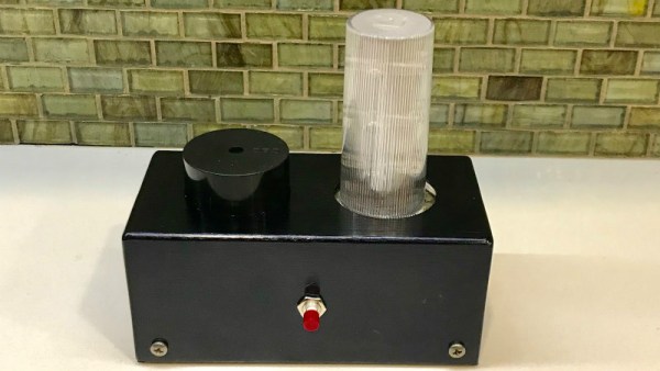
[WhisleyTangoHotel] has taken the basic concept of the Morse clock, which at its most simplistic could be done with a microcontroller and single LED, and expanded it into a (relatively) practical device. With both audio and visual signaling, and support for pulling the time from NTP, this is easily the most polished Morse code clock we’ve ever seen. Using it still requires you to have a decent grasp on Samuel Morse’s now nearly 200 year old encoding scheme of course, but on the bright side, this clock is sure to help keep your CW skills sharp.

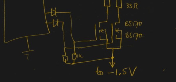
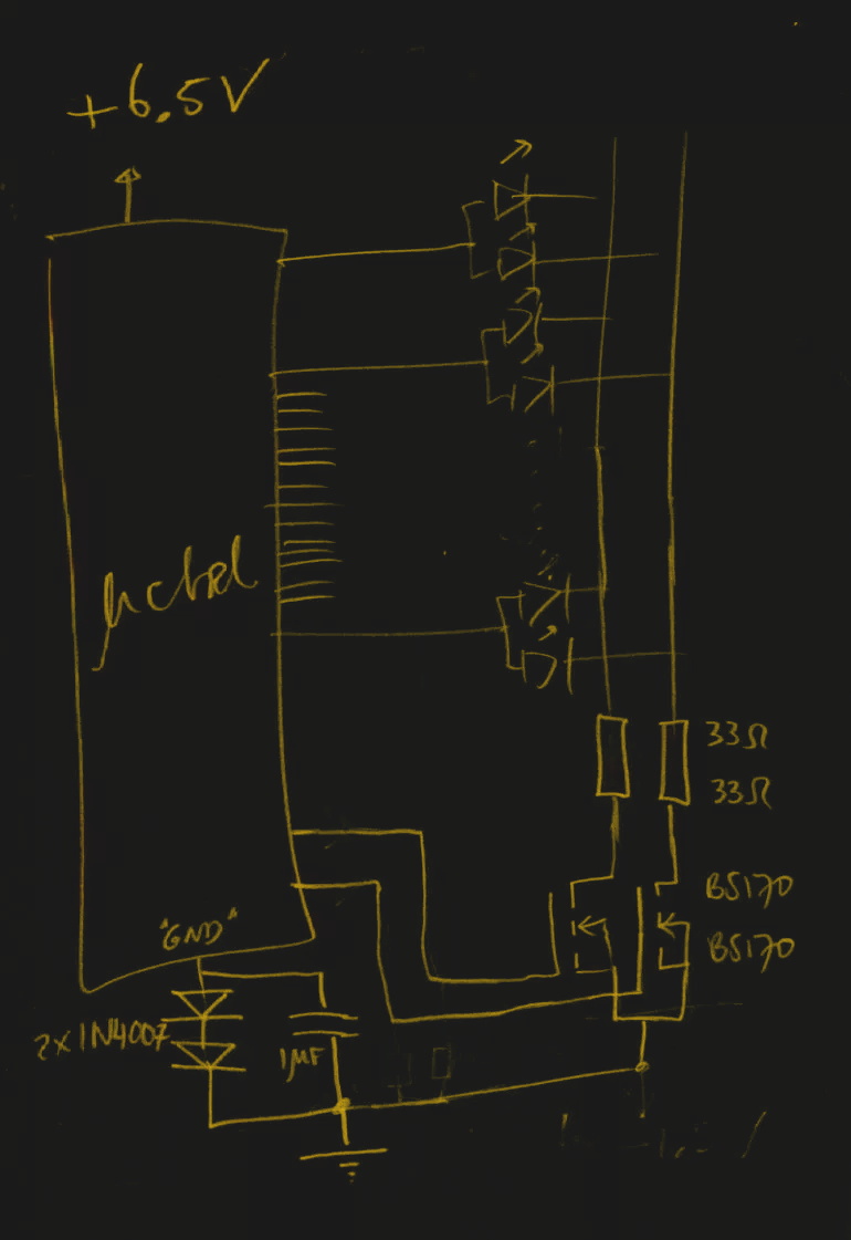
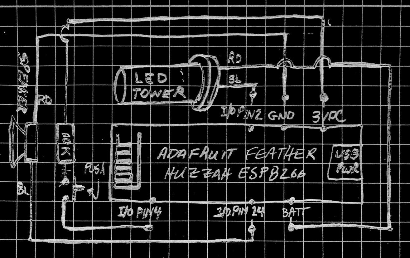
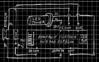
For those following along at home, [WhisleyTangoHotel] provides a hand-drawn diagram to show how everything connects together in his Morse timepiece, but there’s nothing on the hardware side that’s likely to surprise the Hackaday reader. A single momentary push button represents the device’s sole user input, with the output being handled by a LED “tower” and speaker on their own respective pins on the microcontroller. Here a Adafruit Feather HUZZAH is used, but any ESP8266 would work in its place.

Of course, the advantage of using an ESP8266 board over your garden variety MCU is the Wi-Fi connectivity. This allows the clock to connect to an NTP server and get the current time before relaying it to the user. Some might think this overkill, but it’s really a critical feature; the lack of a proper RTC on the ESP means the clock would drift badly if not regularly synchronized. Assuming you’ve got a reliable Internet connection, this saves you the added cost and complexity of adding an external RTC.

[WhisleyTangoHotel] wraps up his blog post by providing his ESP8266 Arduino source code, which offers an interesting example in working not only with NTP and time zones on the ESP, but how to handle parsing strings and representing their principle characters in Morse code.

Interestingly enough, in the past we’ve seen a single LED clock that didn’t use Morse code to blink out the time, which might be a viable option as an alternate firmware for this device if you’re not in the Samuel Morse fan club.

Continue reading “NTP Morse Code Clock Powered By ESP8266”