Solving Grounding Issues On Switch Audio

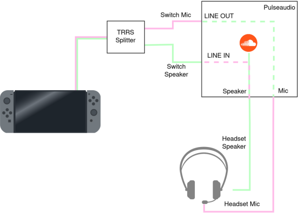
Grounding of electrical systems is an often forgotten yet important design consideration. Issues with proper grounding can be complicated, confusing, and downright frustrating to solve. So much so that engineers can spend their entire careers specializing in grounding and bonding. [Bsilvereagle] was running into just this sort of frustrating problem while attempting to send audio from a Nintendo Switch into a PC, and documented some of the ways he attempted to fix a common problem known as a ground loop.

Ground loops occur when there are multiple paths to ground, especially in wires carrying signals. The low impedance path creates oscillations and ringing which is especially problematic for audio. When sending the Switch audio into a computer a loop like this formed. [Bsilvereagle] set about solving the issue using an isolating transformer. It took a few revisions, but eventually they settled on a circuit which improved sound quality tremendously. With that out of the way, the task of mixing the Switch audio with sources from other devices could finally proceed unimpeded.

As an investigation into a nuisance problem, this project goes into quite a bit of depth about ground loops and carrying signals over various transforming devices. It’s a great read if you’ve ever been stumped by a mysterious noise in a project. If you’ve never heard of a ground loop before, take a look at this guide to we featured a few years ago.

How To Stay Grounded When You Have Zero Potential

Ground is an interesting topic when it comes to engineering. Either it’s the reference level for a digital circuit (not necessarily at zero volts, either), or it’s the return path for current, or it’s the metal chassis, which shouldn’t be the return path for current or else something’s terribly broken. Erika Earl’s talk at this year’s Hackaday Superconference is all about ground.

The first type of ground to talk about is the ground in your outlets and walls. The AC safety ground is the third pin on your plug that should be attached to the chassis of your washer/dryer on one end, and somehow connected to the neutral wire somewhere near your breaker box. The theory of this being if a conductor touches the chassis of a lamp or appliance, all the current will go along that ground bus saving you from electrocution. It should also trip the circuit breaker.

But really we’re rarely dealing with mains power around here. When it comes to electronic design, we’re mostly dealing with analog grounds and digital grounds in circuits. Sometimes these are the same, sometimes they’re not, but they’re both usually referenced to 0 Volts, Add in some considerations for EMC, and ground loops, and you have an astonishing amount of knowledge wrapped up in having zero potential.

If you want to know about what ground actually is, this isn’t a talk to miss. Erika has tons of experience chasing down grounds as an audio engineer, and her career highlights including the director of hardware engineering at Slate Digital and the Senior Technical Engineer at LA’s legendary Village Recording Studios. There’s a lot of experience here, and if you want to where to find your ground, Erika is the person to ask.

Negative Voltage Pushes AVR To New Heights

If we say that a hacker is somebody who looks at a “solved” problem and can still come up with multiple alternative solutions, then [Charles Ouweland] absolutely meets the grade. Not that we needed more evidence of his hacker cred given what we’ve seen from him before, but he recently wrote in to tell us about an interesting bit of problem solving which we think is a perfect example of the principle. He wanted to drive a salvaged seven segment LED display with an AVR microcontroller, but there was only one problem: the display needs 15V but the AVR is only capable of 5V. So what to do?

As it turns out, the first step to solving the problem was verifying there was actually a problem to begin with. [Charles] did some experimentation and found that the display didn’t actually need 15V to operate, and in fact would light up well enough at just 6.5V. This lowered the bar quite a bit, but it was still too high to power directly from the chip.

There were a few common ways to solve this problem, which no doubt the Hackaday reader is well aware of. But [Charles] wanted to take the path less traveled. More specifically, the path with the least amount of additional components he had to put on his PCB. He set out to find the absolute easiest way to make his 5V AVR light up a 6.5V LED, and ended up coming with a very clever solution that some may not even know is possible.

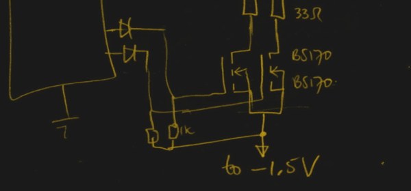
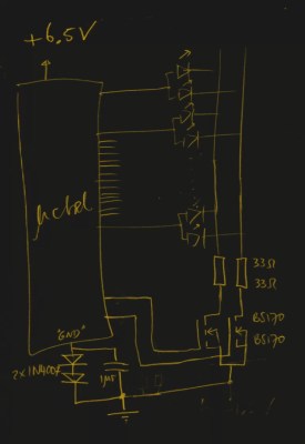
He reasoned that if he connected the source pins of two BS170 MOSFETs to a voltage of -1.5V, even when the AVR pin was 0V, they would be still be receiving 1.5V. This virtual “step ladder” meant that once the AVR’s pin goes high (5V), the relative voltage would actually be 6.5V and enough to drive his LEDs. Of course the only problem with that is that you need to have a source for -1.5V.

Getting a negative voltage would normally require adding more components to the design (which he set out to avoid in the first place), but then he came up with another clever idea. To pull the trick off, he actually feeds the AVR 6.5V, but raises the ground voltage by 1.5V with the addition of two 1N4007 diodes. This way the AVR gets a voltage within its capabilities and still can provide a relative 6.5V to the LEDs.

One might say [Charles] took the Kobayashi Maru approach, and simply redefined the rules of the game. But such is the power of the confounding negative voltage.

Will Hack For Espresso

[Avidan Ross] has an unyielding passion for coffee. Brewing a proper espresso is more than measuring fluid ounces, and to that end, his office’s current espresso machine was not making the cut. What’s a maker to do but enlist his skills to brew some high-tech coffee.

For a proper espresso, the mass of the grounds and the brewed output need to be precisely measured. So, the office La Marzocco GS3 has been transformed into a closed-loop espresso machine with a Particle Photon and an Acaia Lunar waterproof scale at its heart.

Continue reading “Will Hack For Espresso”

Earth Ground And The Grid

The electrical grid transmits power over wires to our houses, and our Bryan Cockfield has covered it very well in his Electrical Grid Demystified series, but what part does the earth ground play? It’s commonly known to be used for safety, but did you know that in some cases it’s also used for power transmission?

Typical House Grounding System

Grounding system normal case

A pretty typical diagram for the grounding system for a house is shown here, along with a few of the current carrying conductors commonly called live and neutral. On the far left is the transformer outside the house and on the far right is an appliance that’s plugged in. In between them is a breaker panel and a wall socket of the style found in North America. The green dashed line shows the normal path for current to flow.

Notice the grounding electrodes for making an electrical connection with the earth ground. To use the US National Electrical Code (NEC) as an example, article 250.52 lists eight types of grounding electrodes. One very good type is an electrode encased in concrete since concrete continues to draw moisture from the ground and makes good physical contact due to its weight. Another is a grounding rod or pipe at least eight feet long and inserted deep enough into the ground. By deep enough, we mean to include factors such as the fact that the frost line doesn’t count as a good ground since it has a high resistance. You have to be careful of using metal water pipes that seemingly go into the ground, as sections of these are often replaced with non-metallic pipes during regular maintenance.

Notice also in the diagram that there are places where the various metal cases are connected to the grounding system. This is called bonding.

Now, how does all this system grounding help us? Let’s start with handling a fault.

Continue reading “Earth Ground And The Grid”

Fixing Faulty But Genuine Apple Power Adapters

apple The standard power adapter for Apple laptops is a work of art. The Magsafe connector has saved more than one laptop owned by the Hackaday crew, and the power brick with interchangeable plugs for different countries is a work of genius. Being a miracle of modern manufacturing doesn’t mean Apple gets it right all the time; the UK adapter doesn’t use the ground plug, leading to the power supplies singing at 50 Hz when plugged in. [Gareth] had had enough of the poor design of his charger and decided to fix it.

The Apple power adapter has two obvious connections, and another shiny metal disk meant for a connection to Earth. In most of the Apple charger ‘extension cords’, this earth connection is provided by the cord. In the smaller plug adapters – even ones where space is not an issue, like the UK plug – this connection is absent.

To fix this glaring oversight, [Gareth] shoved some aluminum foil where the earth terminal on the plug should go. A hole was drilled through the plug to connect this foil to the Earth socket terminal, and everything was covered up with kneadable epoxy.

No, aluminum foil probably won’t do its actual job of preventing horribleness in the event of an insulation failure or short. It will, however, silence the 50 cycle hum emanating from the power adapter, and that’s good enough for [Gareth].

Tube Preamp With A Dazzling Wood Case

It’s been a while since we’ve looked in on the world of vacuum tube audio equipment. [Bruce] just finished documenting a tube preamp he built. He actually made a couple of these with slightly different cases but they use the same circuit design. We found his discussion of common errors made when tying into ground quite interesting. It seems that many folks struggle with noise in their circuits because of ground loops. There’s some details about isolating the signal ground from a metal chassis, and also an admonition about not connecting the input or output jacks directly the chassis.
If you like this, don’t miss on of our favorite tube projects, [Bruce’s] Poddwatt.