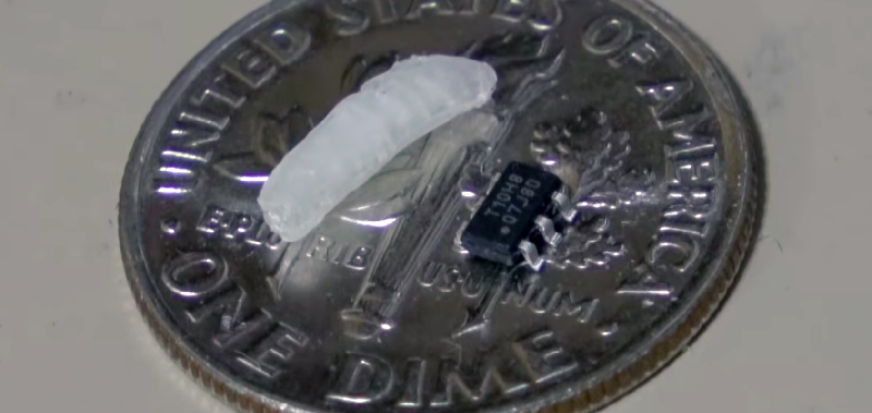
Microcontrollers are small, no one is arguing that. On a silicon wafer the size of a grain of rice, you can connect a GPS tracker to the Internet. Put that in a package, and you can put the Internet of Things into something the size of a postage stamp. There’s one microcontroller that’s smaller than all the others. It’s the ATtiny10, and its brethren the ATtiny4, 5, and 9. It comes in an SOT-23-6 package, a size that’s more often seen in packages for single transistors. It’s not very capable, but it is very small. It’s also very weird, with a programming scheme that’s not found in other chips from the Atmel/Microchip motherbrain. Now, finally, we have a great tutorial on using the ATtiny10, and it comes from none other than [Ben Heck].
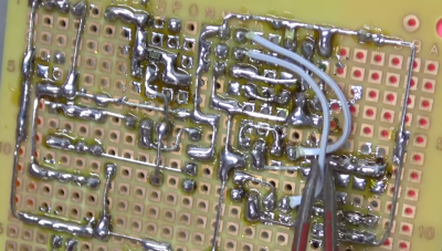
 The key difference between the ATtiny10 and other AVRs is that the tiny10 doesn’t use the standard AVR ISP protocol for programming. Instead of six pins for power, ground, MISO, MOSI, SCK, and RST, this is a high-voltage programming scheme that needs 12 Volts. The normal AVR programmer can do it, but you need to build an adapter. That’s exactly what [Ben] did, using a single-sided perf board, a lot of solder, and some headers. It looks like a lot, but there’s really not much to this programmer board. There’s a transistor and an optocoupler. The only thing that could make this programmer better is an SOT-23 ZIF socket. This would allow bare tiny10s to be programmed without first soldering them to a breakout board, but ZIF sockets are expensive to begin with, and the prices on SOT-23 sockets are absurd.
Programming the device was a matter of loading Atmel Studio and going through the usual AVR rigamarole, but Ben was eventually able to connect a light sensor to the tiny10 and have it output a value over serial. This was all done on a device with only 32 Bytes of RAM. That’s impressive, and one of the cool things about the smallest microcontroller you can buy.


The antenna’s probably bigger than the controller.
DIY SIT23 ZIF here, using re-purposed RJ45 socket contacts. Probably an excellent use for 3D printing, but this one uses wood. https://www.eevblog.com/forum/projects/diy-sot23-zif-socket/
Similar idea using magnets but i’m not sure of the use case – programming it before i solder it just sounds like cruising for a bruising. easier to adapt your operating circuit to accommodate a couple of extra programming connections. I have never regretted building programmability into a circuit
http://notanumber.net/archives/142/simple-reusable-zif-socket-smd-parts
Or you can buy from china at a not so expensive price :
https://www.aliexpress.com/item/Gold-plated-ic-test-block-sot23-6-sot-23-1-7-sot-23-6l-sa717-adapter/32213764577.html
But DIY is more rewarding, indeed.
What is the typical case for these small uC’s? PWM a led (only 2 PWM channels so no RGB? Or some small control loops (it has an ADC and PWM)?
BTW: PIC10f family is also available in sot23-6 package for quite some time..
I don’t know what the killer app for these would be, but I could see using it to drive a stepper motor type automotive gauge from an analog input, a simple sequencer for timing a camera shutter, or some sort of smart nightlight.
It could probably replace a 555 timer in a lot of applications and add some smarts.
A 555Duino?
Waveform generators, small logic cells, some authentication, temp controllers, very basic stuff where making it analog would be big and more expensive.
I did use PIC10F202 to generate noise with LFSR. I designed a PCB that fits behind standard beeper…
They are also used as single panel touch sensors (see AT42QT1010).
*single channel (not panel)
I used PIC10F200 for a small wireless thermal probe:
http://jpa.kapsi.fi/stuff/pix/um_pcb_soldered.jpg
Cool thing :)
I made ATtiny5 to output 8-color VGA ????
https://youtu.be/WdBNR0JEDcY
https://bitbucket.org/jartza/pentaveega/src
Picture of board:
https://drive.google.com/file/d/1r8ypEVNeiNh-ZQWF5ijuuPWbRSO6fRY6/view
U1 is 12MHz oscillator, IC1 is ATtiny5
That board fitting onto the vga connector is super-excellent
Thanks. The “wing” on PCB is actually for power, it plugs straight into USB.
Is the wavering and rolling deliberate or a timing issue?
Everything on screen is delibarate ????
This is what kind of jitter ATtiny5 internal RC creates, which is why I had to add an oscillator…
https://www.youtube.com/watch?v=4XMmc2TIGG0
You can find breakout boards here https://www.tindie.com/products/Rabujan/attiny10-breakout-board/
I used one in a Z80 build to generate an interrupt pulse once a millisecond to keep a timebase. When I was a kid I built crystal radios to fit in ballpoint pen bodies. There must be some amusement to be had by having a computer in your pen or ring. The UI would have to be something like a touch point and LED (or maybe voice?)
https://olduino.wordpress.com/2016/01/15/millisecond-clock-using-attiny10/
The programmer you referred to is way simpler than Ben’s! https://junkplusarduino.blogspot.com/p/attiny10-resources.html
I confess to not having watched the video but certainly if he’s using 12V he’s doing it wrong.
My understanding is a lot of micros have a master clear (MCLR) type input that basically doubles as a reset during operation and a way to hold the micro in programming mode. Now if the fuses/config words are not set to low voltage programming mode this pin is often multiplexed to work as an input and thus would require a high voltage pulse (often 12V) on it to put the chip back into programming mode. If the fuses are set for LV programming mode then this mclr pin is dedicated to allow the micro to hold in reset and thus cannot be used as a general purpose input. I could be wrong but it seems to work this way at least for PIC micros.
@Brian – do you really need 12 volts? That seems very unlikely and i have programmed these things.
A quick look in the datasheet (http://ww1.microchip.com/downloads/en/DeviceDoc/atmel-8127-avr-8-bit-microcontroller-attiny4-attiny5-attiny9-attiny10_datasheet.pdf , 15.3.1 Enabling) reveals: No, you don’t *need* 12V. There’s two methods of resetting the chip into the programming mode, and one of them is applying 12V to the reset pin.
You can set a fuse in the chip that redefines the reset pin for an additional I/O pin. If you set this fuse then the reset pin won’t reset the chip any more, but putting 12V on it will. So if you need the additional I/O pin, you have to use the high voltage programming mode.
I deadbugged a PIC10 with 0603 r,g,b LEDs to make a simple blinky with several selectable modes https://twitter.com/LEDSuit/status/156138376423145474?s=09
I soldered on magnet wire to program it
I got a 403 forbidden on that link – can you check it?
The link worked for me.
[Erik Johnson], now if you could squeeze it all into the push button!
B^)
Now add capacitive touch sensing and remove the hw button :P
What, no love for the WLCSP?
Something like the ATtiny20-UUR has more pins and is even smaller. Though at that point I’m pretty sure you’d be soldering with a needle or something.
Why do people use YouTube to *document* projects like this, it’s about the least useful form other than interpretive dance ffs.
+1 And I wish Hackaday would write (youtube) after the link to warn us.
Yeah – I hate videos for instruction. must be some sort of monetization thing that’s make people use them.
As a kinetic type of learner, videos help me understand the process, but I still want the hardcopy to pour over the details.
My guess is it is part advertising money and part that throwing together a video is often easier than doing a thorough write-up. I used to do full write-ups on my blog but I found hardly anyone would visit and I’d spend hours writing it up so it was hardly worth it. However, I can film, edit and upload a video in an hour and get much more traffic. Not trying to justify it as I personally also prefer reading writeups but that is just the way things are.
I guess. My “blog” such as it is is mostly about me remembering how the hell i did something. video is ok for some things but i need a place to hang pictures and code snippets.
The ATtiny20 is available in WLCSP package, if you want to go smaller. 1.4×1.55 mm. I never used it though.
I put one in the engagement ring I made for my wife (fiancé at that time)
http://embryonic.dk/wordpress/?p=454
Perhaps a better picture of the circuit
http://embryonic.dk/wordpress/wp-content/uploads/2016/04/IMG_20160126_124937.jpg
Did you backlight her diamond or was the LED the entire thing?
Shhhh! She thinks it is a “very special diamond”!
B^)
The LED was the thing. Her work doesn’t allow her to wear jewelry so we already knew that the ring was only temporary. I was using the controller to make the LED pulse slowly.
I couldn’t comment on the blog but nice work. Probably you could use a LED that would be happy and bright at 5ma – good thing you got here to buy in quickly!
The WLCSP Attiny20 makes the Attiny10 look like a dinosaur. It’s the size of spec of dust. More powerful, more GPIOs, and nearly impossible to work with.
https://i.stack.imgur.com/nqqAD.png
That must be fun to solder… (Yeah i know nobody will do this manually.)
It’s been done but you need really really steady hands. https://hackaday.com/2018/06/26/no-caffeine-no-problem-a-hand-soldered-chip-scale-package/
Wow, thats impressive!
A pantograph mechanism should work? Plenty of practical detail to get right though.
Is this the same chip the Chinese used to hack the Supermicro servers?
AVRDude has had support for these for a while and a simple USBasp programmer can be used in-circuit if you can tolerate the gigantic-by-comparison ISP header. I have an ATTiny10 PWMing the heated grips on my motorcycle.
Let’s not forget the 3 cent microcontroller
https://youtu.be/VYhAGnsnO7w
https://microcontroller.com/news/microchip_pic10f.asp
I always thought the Pic 10 is the smallest microcontroller.
The Kinetis KL03 is even smaller, and it’s a 32bit ARM Cortex-M: https://www.eetimes.com/document.asp?doc_id=1321173
The big challenge is CAN HE USE THE QTOUCH PIN IN A PROGRAM ahahhahahhahahahhah