
We are somewhat spoiled because electronics today are very reliable compared to even a few decades ago. Most modern electronics obey the bathtub curve. If they don’t fail right away, they won’t fail for a very long time, in all likelihood. However, there are a few cases where that’s not a good enough answer. One is when something really important is at stake — the control systems of an airplane, for example. The other is when you are in an environment that might cause failures. In those cases — near a nuclear reactor or space, for example, you often are actually dealing with both problems. In this installment of Circuit VR, I’ll show you a few common ways to make digital logic circuits more robust with some examples you can run in the Falstad simulator in your browser.
The most common way to deal with this problem is redundancy. The Space Shuttle, for example, had four computers and at least three had to agree. There was also a fifth computer that could replace a failed computer. The idea is that if one failed, everything would continue to work. The number of computers to use in such a scheme is often a topic of hot debate since with an even number like four, two failures create a dilemma. You can’t know what the right answer is. Many systems use TMR (triple module redundancy) which works just as well in the face of one failure. With two failures it will be wrong, but at least the result is unambiguous.
Voting Logic in a Circuit
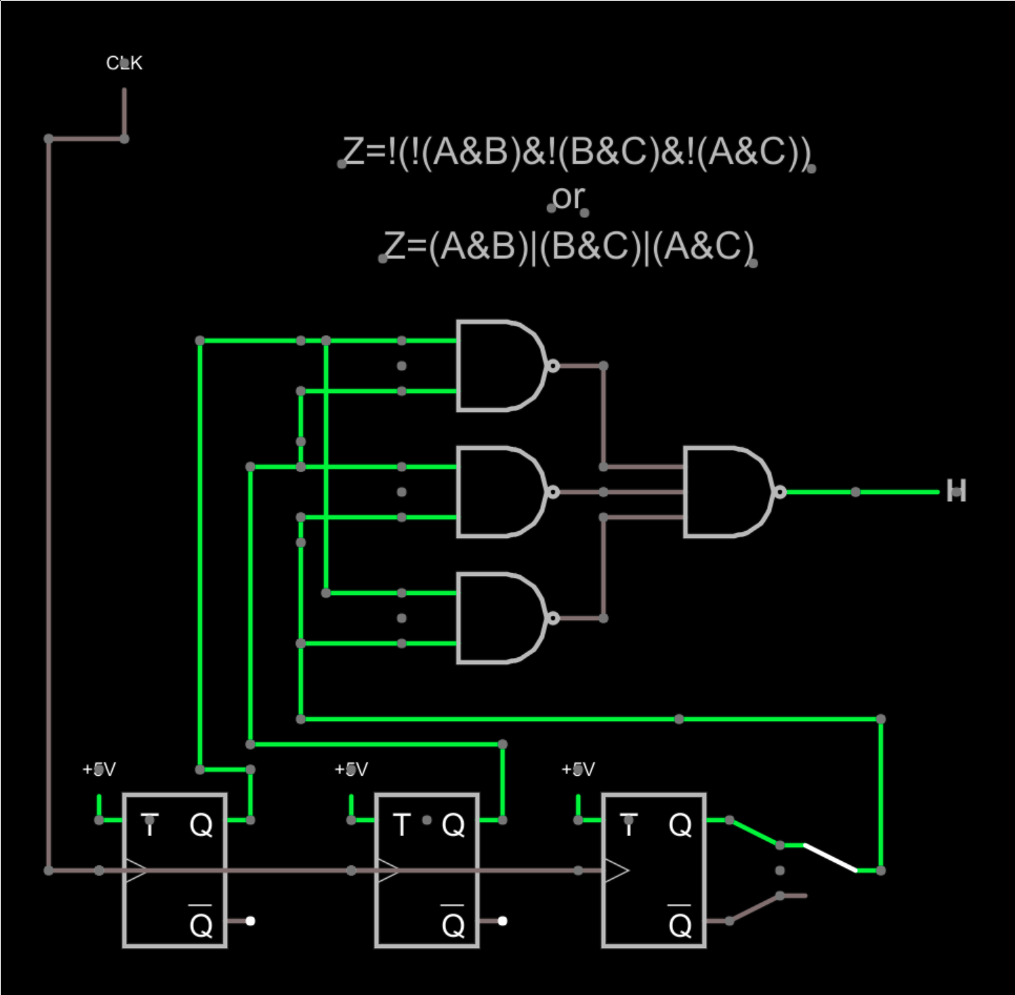
Consider the circuit shown above. The output should be the vote of the three flip flops. The switch to the right lets you inject a failure by selecting the invert output on that one stage, but since the output is the majority of the three flip flops, that switch should have no bearing on the output.
I used T flip flops here, but really they could represent any kind of logic no matter how complex. The key is we expect the same output from them. In fact, there’s no reason each one has to get the answer the exact same way, although that is unusual — usually, the circuits are identical. I drew one clock, but in real life, each would probably have its own private clock, since one clock is a single point of failure.
The logic only uses NAND gates, but if you consider the flip flop outputs as A, B, and C, it is easier to think of the logic as (A&B)|(B&C)|(A&C). If you apply DeMorgan’s theorem you can convert that expression to the NAND gates as shown — they are equivalent.
In English, then, you are saying if any two inputs are high, then the output is high. You don’t need to check A&B&C nor do you need to explicitly test cases where any input is low.
If you try the circuit out, you can see the output will change, and flipping the switch won’t matter. If you break one of the inputs and ground it, for example, then you can see a failure when the switch is thrown because you’ll have two faults instead of one. Even then, the short to ground will be right half the time and the circuit will work. The voter doesn’t care how you got the right answer.
Key Ideas: Eventually You Have to Trust Something
If you think about it, you are implicitly trusting the NAND gates in this implementation. That could be a reasonable thing to do. You might implement the logic using some very robust method — keep in mind that two signals merged with a diode and a pull-up resistor can perform the NAND function if you throw in a single transistor. You could even do the logic (or, at least, the inverter) using relays or using chips that are not as susceptible to failure as other more complex parts. You could also implement the AND/OR version of the circuit pretty easily with diodes only since there is no inversion involved.
 You can also replicate the voting logic. This was done in the Saturn rocket’s computer, for example. However, there’s always some part where you are at that last gate where you generally have a possible single point of failure and you want to make that part as reliable as you can make it.
Eventually, though, you have to trust something. Usually, you will decide to accept a certain number of failures, too. For example, many systems are made to be two-fault tolerant. That is, any two faults will not cause improper operation. The voting we are looking at is one-fault tolerant. Two flip-flops failing will cause the module to produce the wrong answer.
Where to Vote
 It is tempting to try to make everything use TMR. This is a mistake because it drives up complexity and can actually make things worse. In many cases, you should examine the output of your circuits and vote on the outputs only. In some cases (like the Saturn computer) the logic was split into parts and each part was voted. In the particular case of the Saturn computer, there were seven pipelines (each with three copies). Each copy of a particular pipeline fed a voter and the output of the voter fed the next set of three pipelines.
This also can help with glitches that can easily accumulate if you try to vote everything. To follow with the above example, if one pipeline was slightly slower or faster than the other two, you would get small mismatches. By referencing them to the system clock, you could ensure each pipeline had produced its final answer before using the result of the vote.
Using Multiplexers and Error Detection
Another common way to vote is using a multiplexer. Some FPGAs have multiplexers or can configure them quite easily. Here’s a circuit that not only votes, but uses another mux to detect if there is an error.
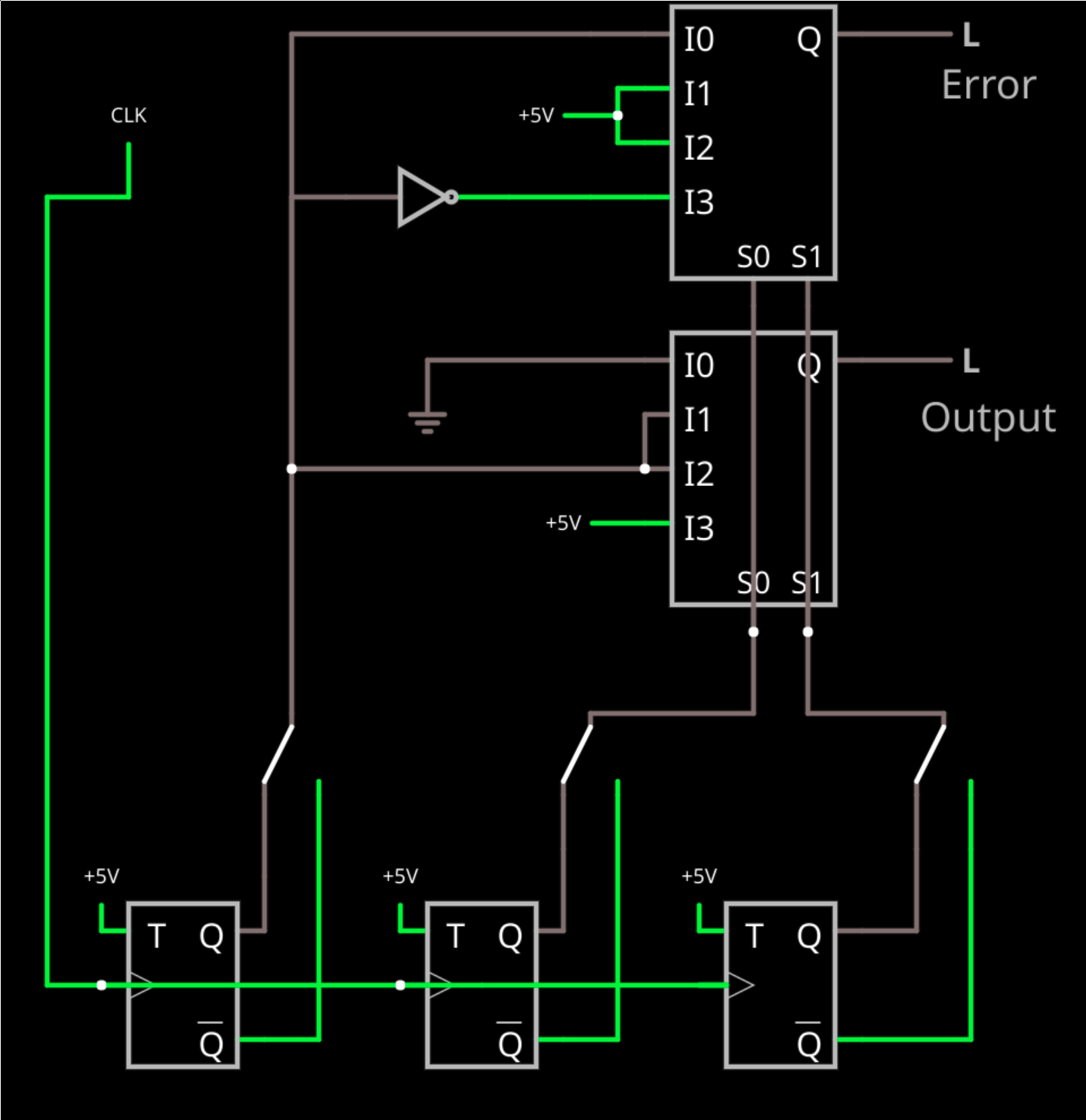
This time I included switches to fail any of the flip flops. Two of the inputs select which mux channel to use (doesn’t really matter which two; I used B and C just to make the layout work nicely). If they are both zero that’s I0 and the output is zero. If they are both high, that’s I3 and the output is high.
The I1 and I2 cases are where B and C don’t agree. At that point, A is the tiebreaker. We just feed it through because that’s the bit that has two votes either way.
The top mux detects an error but needs an inverter (yes, in this case, you could have fed the inverted output of the flip flop in if you didn’t want the fail switch in there). If you have I1 or I2 active then you definitely have some kind of failure because B and C don’t agree. In the cases where they do agree, the output is the state of A — sort of. At I0, there’s no error if A is also 0, so the error signal is A. At I3, there’s no error when A is 1, so we invert A and that’s the answer. You could, of course, work out similar logic with the NAND gates, if you like.
The FPGA/CPU Connection
It isn’t unusual to be doing this kind of logic design on FPGAs. There are several ways this can work. First, there are FPGAs that automatically include TMR flip flops that are very expensive. These usually are known as “space-rated” FPGAs and often have other features such as other radiation-resistant circuitry, redundant clock busses, and so on. While these are expensive, they are very robust and easy to use since you don’t have to specify voting logic and multiple flip flops in your Verilog or VHDL.
Some synthesis tools can be cued to automatically generate TMR flip flops for some or all flip flops in your design. In other words, you specify a flip flop as normal in your VHDL or Verilog and the tool infers three physical flip flops and votes them for you. Exactly how you do this is tool-dependent, but it is likely to be some kind of option or constraint to the synthesis tool. For example, you can see how this works in Synplify in the video below. Even if you don’t use Synplify, the video has some good background information.
Of course, the final option is to do it yourself like we’ve done here. Depending on what you fear, this might not be the best option. One flip flop failing on an FPGA without radiation or some other specific reason isn’t very likely. And if you need radiation tolerance, just doing the flip flops might not be enough.
Keep in mind, though, that I’m only using a single flip flop as an example. You could use this same idea of voting to vote outputs from any odd number of outputs. You could vote three Arduino outputs, for example. Or you might want to vote three sensor inputs although if you were only worried about the sensors you could probably do that in software pretty easily, too. Just don’t forget to account for glitches if the outputs are not exactly synchronized.
For More Information
Dealing with redundant circuits is a huge topic and I can’t hope to cover everything in a short post. If you want to read more, NASA has quite a few documents that can help you including some discussions of the Shuttle architecture with failure reports and some scholarly papers. If you want to learn more about other kinds of redundancy and why adding redundancy can lower reliability if you aren’t careful, you can check out the Wikipedia article or this page from Rutgers. Specialists spend years studying this kind of design and you still find arguments over what’s the best for any given application. So don’t expect to master this overnight.
Especially since there’s plenty more to consider when making a really robust system. For example, a good design will periodically refresh the outputs so that an error that would correct itself won’t accumulate. Memory probably needs periodic scrubbing and error correction. But these simple circuits are at the heart of some of the most reliable systems we know how to make.


While this article was about hardware redundancy I think a mention of software redundancy would have been nice. For instance, the space shuttle has 5 AP-101 computers. During normal operation three of the computers are actively controlling the mission and a fourth is powered on but in an idle state as a hot backup. The fifth is powered down as a cold backup. Each of these computers can operate the shuttle all on its own, but in normal operation they use the voting method described in the article implemented in both hardware and software.
The really interesting part of the software redundancy is not the voting (although that is interesting in it’s own right), the interesting part of the software redundancy is that four of the computers run the exact same software, but a fifth actually runs completely different software, written to the exact same specs by a completely different group that has no interaction with the other. The software has to pass the same testing, review, and verification process and is functionally equivalent. The thinking is that if there is a crippling bug in one version of the software it is very unlikely the same bug would exist in the other version.
The vast majority of the telephone network other than subscriber lines has redundancy and error-checking at some level, and circuits like this are all over.
Most optical stuff is 1:1 redundant with ring architectures, so it’s protected against both optics failure and fiber failure. In the machines I worked on, the failover logic could be configured, obviously if the E-W path fails the W-E path gets used, but what about when E-W comes back up, do we revert or remain?
Circuit-switched networks all had two copies, both connected to all the line-equipment shelves. Logic in each shelf would determine which copy to listen to. One copy could be taken down for maintenance (always performed at night, just in case) without affecting traffic.
Even the line-equipment cards typically had n+1 copies, with relays to swap signals over to the spare card. Out of tens of thousands of circuits I turned up, hundreds of line cards and dozens of power supplies that suffered infant mortality failures, I only saw *one* bad relay. You had to trust the relays, but that was an exceptionally solid bet.
This is always fascinating. Years ago, I worked on some early telecommunications equipment where the condition of the output was extremely important. The design of the circuitry was such that it would catch any single component failure. It was really old tech, germanium transistors, etc. the complexity was far simpler than any computer but it was a digital device. Not only did the design have to follow all the EE rules but it would also detect when it didn’t work and the design was just beautiful. It was the first time I stood awestruck in the face of genius. Someone poured their heart and soul into the design of that machine and it showed because it was operational for a long, long time.
The logic of the system is fine, but it fails to take into account real components that fail in ways the abstraction doesn’t.
For example, a flip-flop doesn’t necessarily fail in an 1/0 state, but can have any voltage in between, and source or sink any amount of current, which makes the behavior of the subsequent circuit unpredictable because the effective logic state of the input can be determined by the amount of current/voltage the circuit expects to get, which may be determined by the other inputs (especially with diode-resistor logic), which makes the system liable to run into oscillations and chaotic states.
To make an example, I recently had to troubleshoot a circuit that implemented a rudimentary comparator using two NPN transistors. It was “working”, but not switching at the voltages determined by the circuit diagram. Turns out, one of the transistors was reversed, and the funny thing about BJTs is that they work perfectly fine while reversed – only the amplification of current is reduced to ~1 so the collector current is approximately the same as the base current, and that fudged up the circuit.
If in a voting device, a transistor were to be damaged in a way that made it behave in this manner, the inputs to the logic would suddenly start to depend heavily on how much current is available to it – with some inputs it would read something, and with other inputs another thing. A terrible bug to discover.
Logic generally uses FETs instead BJTs. Although the voltage itself may float a bit, the next FET along will still only see ‘HIGH’ or ‘LOW’ unless it managed to find and remain in a very specific, thin region.
Good point though, error correction and detection is much harder in analogue circuits.
Good stuff. I think Robert Heinlein had 3 way voting in his science fiction in the late 1940’s and 1950’s. He had been a naval gunnery expert. Maybe they used something like this in the gun directors?
I doubt he was a gunnery expert. From memory he was only in the Navy a couple of years before he got tuberculosis and worked on an aircraft carrier and a destroyer in his short career. I think he was an engineer though.