4-bit Relay Logic Counter Begs To Have Its Buttons Pushed

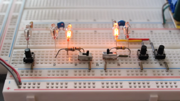
What’s one to do with some nice little relays of questionable pinout, and prototyping board? How about a quietly clicky 4-bit counter using relay logic with tons of buttons?

The register with LEDs and buttons is on the top board, the incrementer on the bottom board.

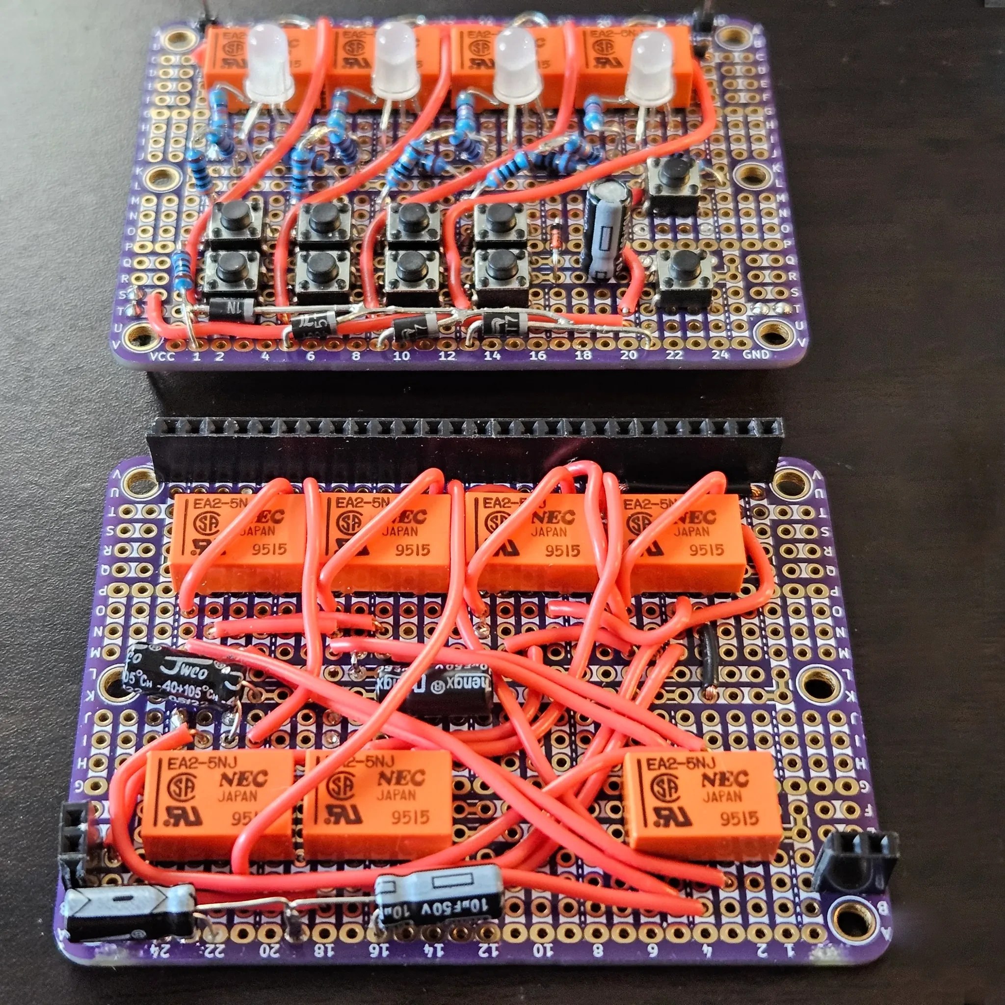
[Agatha Mallett] made the counter after finding herself in possession of a quantity of relays burdened by terrible documentation (the datasheet shockingly lacks a pinout, and doesn’t even mention the coil being unidirectional). But since the relays are also small and of decent quality, they were a good candidate for a small relay logic-based project.

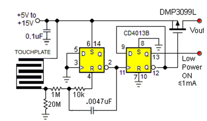
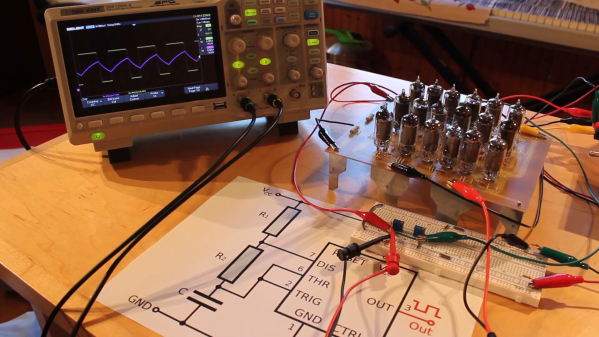
The key to the build is implementing D-type flip-flops using relays. This is done by holding the coil voltage of each relay between its set and release voltage levels. A small voltage bump will energize the coil, closing the relay and leaving it closed. Conversely, a small negative spike releases the coil, leaving it open. This forms the basis of the counter, and [Agatha] has a separate write-up all about the details of using relays in this way.

Implementing this was rather less straightforward than it may sound because it relies on balancing the coils of many relays on a figurative knife-edge of voltage, but not every component is perfectly identical. A tweaked resistor or capacitor here and there was needed before things settled into reliability.

The end product has indicator LEDs, buttons to increment or clear the current count, and it even has buttons to set or clear individual bits. This is a project that begs to be interacted with, and there’s a short video on the project page so you can watch it go through its paces.

Thanks to [Jess] for the tip!

Flip Flops Make Great Soft Switches

Mechanical switches are pretty easy to understand—the contacts touch, the current flows, and Bob is, presumably, your uncle. But what about soft switches? Well, they’re not that difficult to understand either, as explained by [EDN].

You can build a touch switch quite easily with old-school chips.

The traditional softswitch takes input from a momentary single-pole pushbutton and lets you press to toggle power on and off. This operation is easy to achieve with a simple flip-flop constructed with old-school logic to create a “bistable” circuit. That means it will happily remain stable in one of two states unless you do something to make it switch.

Continue reading “Flip Flops Make Great Soft Switches”

Single-Stepping The 6502 Processor

Although marketing folk and laypeople may credit [Steve Jobs] as the man behind the success of Apple, those in the tech world know the real truth that without [Steve Wozniak] nothing would have ever gotten off the ground during the early days of the computer company. As an exhibit of his deep knowledge of the machines he was building, take a look at this recreation of a circuit by [Anders] which allows the 6502 processor to step through instructions one at a time, originally designed by [Woz] himself, even though there are still myths floating around the Internet that this type of circuit can’t work.

Like a lot of Internet myths, though, there’s a kernel of truth at the middle. The original 6502 from the mid-70s had dynamic registers, meaning they would lose their values if the chip was run below a critical clock speed. Since single-stepping the processor is much lower than this speed, it seems logical that this might corrupt the data in the registers. But if the clock is maintained to the registers the processor can be halted after each instruction, allowing even the original 6502 to go through its instructions one at a time.

[Anders]’s project sets up this circuit originally laid out by [Steve Wozniak] but updates it a bit for the modern times. Since the technology of the era would have been TTL, modern CMOS logic requires pull-up resistors to keep any inputs from floating. The key design of the original circuit is a set of flip-flops which latch the information on the data bus, and a switch that can be pressed to let the processor grab its next instruction, as well as a set of LEDs that allow the user to see the value on the data bus directly.

Of course, a computer processor of this era would be at a major handicap without a way to debug code that it was running, so there are even dedicated pins that allow this functionality to occur. Perhaps the Internet myth is a bit overblown for that reason alone, but [Anders] is no stranger to the 6502 and has developed many other projects that demonstrate his mastery of the platform.

Continue reading “Single-Stepping The 6502 Processor”

This Unique Flip-Flop Uses Chemistry And Lasers

One of the first logic circuits most of us learn about is the humble flip-flop. They’re easy enough to build with just a couple of NOR or NAND gates, and even building one up from discrete components isn’t too much of a chore. But building a flip-flop from chemicals and lasers is another thing entirely.

That’s the path [Markus Bindhammer] took for his photochromic molecular switch. We suspect this is less of an attempt at a practical optical logic component and more of a demonstration project, but either way, it’s pretty cool. Photochromism is the property by which molecules reversibly rearrange themselves and change color upon exposure to light, the most common example being glass that darkens automatically in the sun. This principle can be used to create an optical flip-flop, which [Markus] refers to as an “RS” type but we’re pretty sure he means “SR.”

The electronics for this are pretty simple, with two laser modules and their drivers, a power supply, and an Arduino to run everything. The optics are straightforward as well — a beam splitter that directs the beams from each laser onto the target, which is a glass cuvette filled with a clear epoxy resin mixed with a photochromic chemical. [Markus] chose spiropyran as the pigment, which when bathed in UV light undergoes an intramolecular carbon-oxygen bond breakage that turns it into the dark blue pigment merocyanine. Hitting the spot with a red laser or heating the cuvette causes the C-O bond to reform, fading the blue spot.

The video below shows the intensely blue dot spot developing under UV light and rapidly fading thanks to just the ambient temperature. To make the effect last longer, [Markus] cools the target with a spritz from a CO2 cartridge. We imagine other photochromic chemicals could also be employed here, as could some kind of photometric sensor to read the current state of the flip-flop. Even as it is, though, this is an interesting way to put chemistry and optics to work.

Continue reading “This Unique Flip-Flop Uses Chemistry And Lasers”

Neon Lamps — Not Just For Pilot Lights

It’s easy to see why LEDs largely won out over neon bulbs for pilot light applications. But for all the practical utility of LEDs, they’re found largely lacking in at least one regard over their older indicator cousins: charm. Where LEDs are cold and flat, the gentle orange glow of a neon lamp brings a lot to the aesthetics party, especially in retro builds.

But looks aren’t the only thing these tiny glow lamps have going for them, and [David Lovett] shows off some of the surprising alternate uses for neon lamps in his new video. He starts with an exploration of the venerable NE-2 bulb, which has been around forever, detailing some of its interesting electrical properties, like the difference between the voltage needed to start the neon discharge and the voltage needed to maintain it. He also shows off some cool neon lamp tricks, like using them for all sorts of multi-vibrator circuits without anything but a few resistors and capacitors added in. The real fun begins when he breaks out the MTX90 tube, which is essentially a cold cathode thyratron. The addition of a simple control grid makes for some interesting circuits, like single-tube multi-vibrators.

The upshot of all these experiments is pretty clear to anyone who’s been following [David]’s channel, which is chock full of non-conventional uses for vacuum tubes. His efforts to build a “hollow state” computer would be greatly aided by neon lamp circuits such as these — not to mention how cool they’d make everything look.

Continue reading “Neon Lamps — Not Just For Pilot Lights”

Should’ve Used A 555 — Or 276 Of Them

When asked to whip up a simple egg timer, most of us could probably come up with a quick design based on the ubiquitous 555 timer. Add a couple of passives around the little eight-pin DIP, put an LED on it to show when time runs out, and maybe even add a pot for variable timing intervals if we’re feeling fancy. Heck, many of us could do it from memory.

So why exactly did [Jesse Farrell] manage to do essentially the same thing using a whopping 276 555s? Easy — because why not? Originally started as an entry in the latest iteration of our 555 Contest, [Jesse]’s goal was simple — build a functional timer with a digital display using nothing but 555s and the necessary passives. He ended up needing a few transistors and diodes to pull it off, but that’s a minor concession when you consider how many chips he replaced with 555s, including counters, decoders, multiplexers, and display drivers. All these chips were built up from basic logic gates, a latch, and a flip-flop, all made from one or more 555s, or variants like the 556 or 558.

As one can imagine, 276 chips take a lot of real estate, and it took eleven PCBs to complete the timer. A main board acts as the timer’s control panel as well as serving as a motherboard for ten other cards, each devoted to a different block of functions. It’s all neat and tidy, and very well-executed, which is in keeping with the excellent documentation [Jesse] produced. The whole thing is wonderfully, needlessly complex, and we couldn’t be more tickled to feature it.

Continue reading “Should’ve Used A 555 — Or 276 Of Them”

Should Have Used A Vacuum Tube 555

“You should have used a 555” has become a bit of a meme around these parts lately, and for good reason. There seems to be little that these ubiquitous chips can’t be used for, and in a world where code often substitutes for hardware, it’s easy to point to instances where one could have just used a simple timer chip instead.

Definitely not in the meme category, though, is this overkill vacuum tube 555 timer. It comes to us via [David Lovett], aka [Usagi Electric], who has lately caught the “hollow state” electronics bug and has been experimenting with all sorts of vacuum tube recreations of circuits we’re far more used to seeing rendered in silicon than glass. The urge to replicate the venerable 555 in nothing but vacuum tubes is understandable, as it uses little more than a pair of comparators and a flip-flop, circuits [David] has already built vacuum tube versions of. The only part left was the discharge transistor; a pentode was enlisted to stand in for that vital function, making the circuit complete.

To physically implement the design, [David] built a large PCB to hold the 18 vacuum tubes and the handful of resistors and capacitors needed. Mounted on eight outsized leads made from sheet steel, the circuit pays homage to the original 8-pin DIP form of the 555. The video below shows the design and build process as well as testing of all the common modes of operation for the timer chip.

You can check out more of our coverage of [David]’s vacuum tube adventures, which started with his reverse-engineering of an old IBM logic module. And while he did a great job explaining the inner workings of the 555, you might want to take a deeper dive into how the venerable chip came to be.

Continue reading “Should Have Used A Vacuum Tube 555”