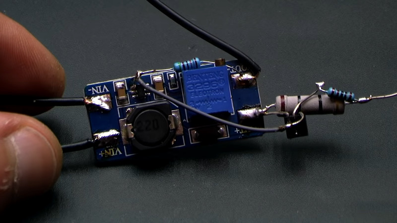
The MT3608 is a popular boost converter, able to easily step up DC voltages in useful ranges, at an incredibly low cost. Modules can be sourced from eBay for less than $2, built on a PCB, ready to go. One drawback of these modules, particularly when working with batteries, is the idle current draw, on the order of 1 to 1.5mA. Fear not, however — there is a workaround, courtesy of [Aka Kasyan]. (Video, embedded below.)
The trick is to modify the behavior of the converter when no load is connected. The enable pin of the boost converter is held low through a pull-down resistor, keeping the boost converter switched off. In this state, the output voltage is equal to the input voltage. A current sense resistor is then installed in the output path. When a load is connected, this causes a voltage drop across the current sense resistor. This is then used to switch a transistor, which then connects the enable pin to the positive rail, switching the converter on, leading to the full boosted output voltage being reached.
[Aya] reports that this drastically cuts the idle current draw, which is particularly useful for battery powered projects. It’s important to note that the current sense resistor must be appropriately sized for the given load, however. If you’re a little hazy on the background, fear not — we’ve discussed the nature of boost converters before. Video after the break.
[Thanks to Baldpower for the tip!]


please, add a “video” tag
please
please
Yes.
That would help.
What for? A huge majority of the posts here have video, and for some it’s the entirety of the source.
If you read HAD on a phone using a slow mobile data network, and on a limited data plan, eg on a train or in a coffee shop or cafe, you do not want to go starting videos. And of you live in a rural location with almost unusably slow broadband, you do not want to go starting videos.
Vector formats like Flash were made for…back in the day. Shame we’ve gotten away from that in this era of plenty.
You can always read the summary and bookmark it for later. What’s the alternative, skip it altogether?
“Have video” != “are only video”
video + text => good
video only => useless
+100 How difficult can it be?
Different paygrade between youtube expert and article editor.
It would have been nice to have a picture of the schematic embedded within the article, that makes discussing it much easier.
Nice touch, a limitation: as mentioned, it introduces a voltage drop of 0.65 V (or so). This voltage drop is current dependent, so you can’t really regulate this away easily using the variable resistor.
There is a thing you can do to improve this:
( have a look at the schematic here: https://www.sunrom.com/media/content/1118/MT3608-schematic.gif or here:
https://youtu.be/zJJcdptSH80?t=186)
1) still use a resistor between the output terminal and the load, but instead of connecting the emitter of the transistor to the output, connect it at the terminal between the coil and the diode. This has the effect that the voltage drop of the diode also helps in getting tot the 0.6V required to turn on the transistor. Depending on load, the forward voltage of the diode is 0.2 V and higher (https://www.onsemi.com/pub/Collateral/SS39-D.PDF, figure 3)
So the external resistor only needs to add 0.4V or so, which is less what it was before.
The circuit may need an extra capacitor between the base of the transistor to earth to counter any high frequencies that originate from the switching. It all depends on the delay of the enable pin.
Or even better:
2) Lift the diode of its pad at the connection to the output, and insert your current sense resistor in series with the diode. Then put your transistor over either the current resistor, or over the diode and current resistor, as described before.
Because you have moved the current resistor _before_ the voltage regulation network, once the regulator is turned on, the output voltage will be exactly where you want it. Explicitly said: the current regulation network will see a lowered voltage because of your added resistor and will increase the output to compensate for the voltage drop caused by it. That’s its job.
It may need an extra capacitor between the base of the transistor to earth to counter any high frequencies that originate from the switching. It all depends on the delay of the enable pin.
Or an easy summary of the above: cut the connection between VD1 and R1, and connect R1..C2 behind your current sensing resistor with a wire.
Argh – couple of weeks too late. Killed a bunch of 18650s with one of these leeching away. Super handy solution though – straight to the pewl room.
Get the 18650 protected versions that won’t drain to zero. Or overcharge. Great for solar power too. You might be able to recover the 18650 if you try charging very slowly at <50 mA. Set your power supply to 4.2V and 50 mA. I've successfully recovered dead Lithium's this way. And they have stayed functional too… a year later. Just NEVER try to charge them normally until recovered and recharged fully.
Yea – found they’re really hard to get with tabs. Rolled the dice on the unprotected cells (on solar) and lost. Need to get a current regulated power supply…
China has single cell 18650 holders…. like the kind for AA cells. Cell protection boards are available on their own too. Or you insert the protected version into the holder…. If you have the space.
The resistor needs to drop at least 0.6V in the “converter-off” situation. So, if, like in the example, you have 4V input and 15V out, and the load is resistive like the lamp, then you’ll be dropping about 2.3V across the resistor when the thing is on.
A better circuit would use a smaller threshold and add a diode to limit the voltage drop across the resistor. Which brings me to the “hack”: use the diode already in the circuit. when there is very little current draw the voltage across the diode will be smaller as well. In the video it was 110 mV. If you can use that to sense on/off that would be even better.
ooh neat
Only problem is the diode sees pulsing current when the converter is running, so it would need a low-pass filter to keep the PWM controller from going crazy.
HaD, I hate to say it but you need to screen the videos you link into the article. That video had a one minute ad by the narrator, shilling a sponsor board house, within 45 seconds of the video starting. I understand a quick 5 second shout out to a sponsor, but not a one minute ad.
Bwa, you can skip it…
Screen them? What would they do in these cases, drop the article? I’d rather have it, maybe with a comment saying when the interesting part starts.
Link to after the ad, with a note that they did so. Folks who want to see the add can go back to the beginning, the rest of us can enjoy the relevant bits.
The video belongs to the authors and it is posted on the authors Youtube channel, so nobody except the autors have authority and jurisdiction over it. Get over it and keep going, friend
Also, Hackaday has been bought by another company a couple years ago, so it has become much more commercial than ever (meaning they have to push articles at any cost – so do not expect much screening of the content)
Bet they would if they were selling screen doors. :-D
I just don’t get people who complain that they want video content to be fast and cheap/free to cater to their needs. Your time isn’t so important that it trumps a video creator’s need to get compensated for the time and effort they put into a video. It isn’t so much to ask that you either a) sit through a 60 second ad, or b) fast forward through it so that creators can afford to keep making videos. I get the knee jerk response, I hate long ads in videos too, but ultimately I understand why creators need them and I’d rather creators keep making videos than not.
Because I’m super dilligent, the video link at the top of the article starts at t=101 seconds, skipping the preroll ad.
Unfortunately due to embed limitations (either by WordPress or Youtube, I am unsure) this didn’t work for the video embedded after the break.
For a 12V output, the 0.6V drop across the sense resistor will only be ~5% of the output voltage, so will reduce efficiency of 5%. Not much of a penalty for powering down when there is no load. But it still doesn’t provide short circuit protection. I suppose if you wanted it “off” you’d add a switch to the input, rather than power it down, but I wonder how many applications would idle at the input voltage (minus the schottky diode drop), but require a higher voltage to run? Why not just use a $0.40 micro with a button to enable/disable?
One way to reduce the burn voltage across the sense resistor is to add a schottky diode. Meaning one only needs ~0.2-0.3 drop across it. Not really worth it for a 203% gain in efficiency though.
OK, just for the record: We add 10Ω to the *regulated* output of a *voltage regulator*, which was designed to make a source look like a *voltage source* giving the *same voltage* regardless of current draw over a full range?
That’s like the opposite of helping, man.
You could move the feedback divider to after the current sense resistor to compensate for the shunt voltage drop.
But for a resistive load will it go into runaway trying to regulate the voltage since the current will keep increasing as the voltage increases?
Might be better to use a really small, milliohm current sense resistor and an amplifier across it.
I am wondering if the circuit arrangement used in Fig.17 of the Texas TPS61040 datasheet would be a more efficient method of no-load shutdown when applied to the MT3608.
http://www.ti.com/lit/ds/symlink/tps61040.pdf
The output voltage adjustment values could be as on the MT3608 converter module since they are isolated by the transistor when no load is connected and thus the circuit would draw almost zero current.
I would like to boost +5V to +20V for a very loud piezo buzzer.
Any idea what the current draw would be for this boost convert to get to +20V @ 20mA ?
thanks
Hi, i am using this module in mp3 audio shouter which i control by Atmega32P controller when someone in front of ultrasonic sensor it will play the audio, i want make power efficient system but when i use power supply for 10W amplifier tda2030 at 6-12v then it work fine when i am using battery lipo battery 3.7 v for power up with this boost boost 3.7v – 9v it will fluctuating and not working kindly also drawing upto 1.5 ampere current.