Everyone loves NeoPixels. Individually addressable RGB LEDs at a low price. Just attach an Arduino, load the demo code, and enjoy your blinking lights.
But it turns out that demo code isn’t very efficient. [Ben Heck] practically did a spit take when he discovered that the ESP32 sample code for NeoPixels used a uint32 to store each bit of data. This meant 96 bytes of RAM were required for each LED. With 4k of RAM, you can control 42 LEDs. That’s the same amount of RAM that the Apollo Guidance Computer needed to get to the moon!
His adventure is based on the thought that you should be able to generate these signals with hardware SPI. First, he takes a look at Adafruit’s DMA-Driven NeoPixel example. While this is far more efficient than the ESP32 demo code, it still requires 3 SPI bits per bit of NeoPixel data. [Ben] eventually provides us with an efficient solution for SPI contro using a couple of 7400 series chips:
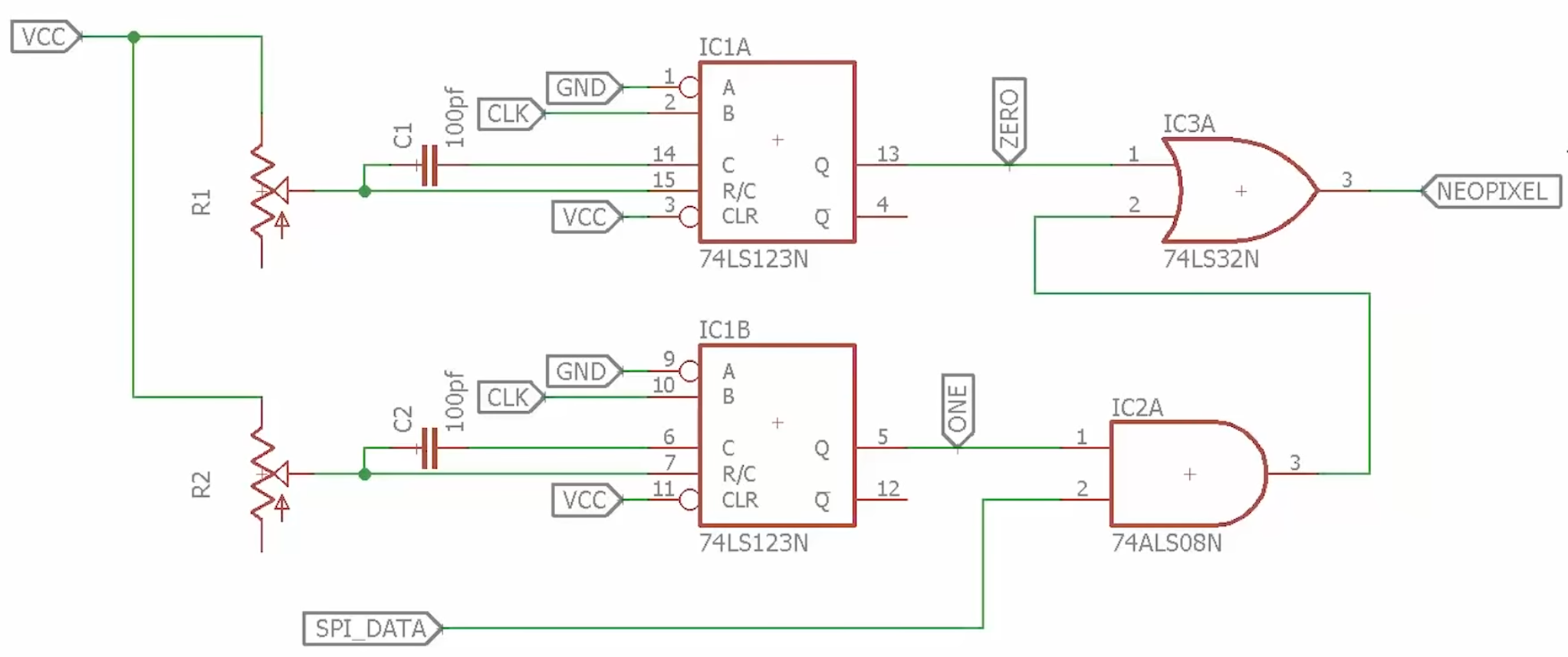
[Ben]’s solution uses some external hardware to reduce software requirements. The 74HC123 dual multi-vibrator is used to generate the two pulse lengths needed for the NeoPixels. The timing for each multi-vibrator is set by an external resistor and capacitor, which are chosen to meet the NeoPixel timing specifications.
The 74HC123s are clocked by the SPI clock signal, and the SPI data is fed into an AND gate with the long pulse. (In NeoPixel terms, a long pulse is a logical 1.) When the SPI data is 1, the long pulse is passed through to the NeoPixels. Otherwise, only the short pulse is passed through.
This solution only requires a 74HC123, an AND gate, and an OR gate. The total cost is well under a dollar. Anyone looking to drive NeoPixels with a resource-constrained microcontroller might want to give this design a try. It also serves as a reminder that some problems are better solved in hardware instead of software.
[Thanks to Baldpower for the tip!]


Another possible solution is to switch to APA102 (DotStar) LEDs and simply use SPI directly, like a civilized man.
That is exactly what I was thinking, and you can clock Dotstars at up to 32Mhz, or at any rate you want for that matter.
But hey.. he did do something new. I appreciate that part.
These are a lot of less common and more expensive than the ubiquitous WS2812b (and its clones) based LEDs. If you really need SPI, it is often cheaper to add a small micro to a string of WS2812b to do the translation for you than to switch to APA102 LEDs.
Reminds me of a old server I had that refused to use a display size larger than 640×480 with no display attached (remote desktop) despite all kinds of driver hackery attempts.
Solution was a vga dummy consisting of three 75 ohm resistors, each one over a color output in the vga plug.
Then the server gladly accepted whatever resolution you wanted it to display.
That’s slightly different, when developers/engineers try to fix problems that don’t exist or think they know better than the end user. Or executive/fiscal meddling.
Define “better”. While often hardware is indeed better, I do not agree that this hardware solution is better for anything other than a hack for personal use. Having to rely on RC timing for pulse lengths is a horrible idea, plus an added cost of less than a dollar is a large price to pay if you’re mass producing something. Better to add a low cost micro for repeatable results.
I was just going to say this. Ben’s solution will work on a bench but good luck keeping it working long term, especially in places where there is vibration or temperature changes! A much better solution is to use a hw timer + interrupts with a small state machine in the interrupt handler to set it to generate the timing periods (which actually need to be quite accurate!).
This SPI hack also doesn’t quite solve the originally described problem of using uint32_t for each LED (the LEDs need 24bit of data) in any way – you still need to store the data somewhere, regardless of whether they are being sent out using SPI or something else. His solution still uses 3bytes/pixel, effectively a byte array – the same thing that could be achieved using that timer above, with no additional external hw and with much better long term reliability (no pots that can change value or capacitors that age …)
The Adafruit’s DMA thing is a gross hack, effectively abusing SPI to replay the pulse patterns instead of sending actual bytes out. It is convenient because the hardware takes care of everything when sending the data out but the data preparation is a pain and it requires a ton of RAM.
Perhaps he should first check the work of Cnlohr – his colorChord is able to drive 521 LEDs from ESP8266 while doing Fourier transformation on audio input signal ;)
µs is microseconds not ns nanoseconds?!
It’s also possible to use the CLC and PWM blocks in a PIC to implement the logic in addition to the SPI block.
Ah, I see you are a man of culture as well!
Ahh, I was just thinking this was probably possible, and was about to make a post to this effect before I saw your post. The CLC feature of some PICs is pretty neat that way.
Elegant solutions involving PIC peripherals is why Microchip is #1.
I got nervous when I saw the R’s and C’s attached to 7400 TTL so I took a look at the 74LS123 design guide. I am not sure of the timing tolerances but device to device variations looked to be about -5 to +4% so roughly up to a 10% variance from chip to chip. The thermal stability as one would expect also was not really good. I noticed that HC parts were listed in the write up while LC parts were called for in the schematic.
As a former designer of industrial electronics, this is the type of engineering that makes me very nervous. Someone gets one that works on their test bench and says “good” lets roll them out. A lot of them may be fine when tested. A lot of them may fail when tested with no parts out of spec. And a lot of them may fail if they are put into service with any large thermal variations,such as in a car.
I am not saying this will not work, but this strikes me as the type of design where you will have issues The cap tolerance, parasitics, and chip to chip variation make me nervous.
True, and cheap capacitors have a tolerance of 20 percent right off the shelf.
Yep. I bet that this will require a constant tweaking of those pots with the tongue at just the right angle. Ben should, IMO, know better than to present something like this to unsuspecting newbies.
There is some tolerance in the required pulse lengths and the clock frequency. The length of the low phase is not important as long the clock frequency is not excessively high or so low that the latching is triggered. Only the description in the datasheet reads quite complicated.
Any time you have 2 trimpots in a product, they’ll cost you money to trim them manually and be a bottleneck at the end of a production line.
Meh. Passive components left out of the cost estimate. Pots and an “unusual value” caps. And PCB space.
I’d bet you could get a $0.50 microcontroller to convert a known-frequncy SPI data line (one wire; save a pin on some micros) to NeoPixel datastream. Well, I’d bet that someone like AtomicZombie could do it…
One of the Chinese 8051s mentioned the other day could do it without breaking a sweat, so $0.22
Plus there is allready an ws2812 example for the CH55x $0.22 micro available here:
https://github.com/Blinkinlabs/ch554_sdcc/tree/master/examples/ws2812
If you can already do hat with a $0.25 micro, why bother with converting SPI data from a larger one. :P
In my case, the 8051 was a ‘second processor’ inside a (slightly larger) SOC, so ideal to use as a WS2812 manager while the main processor got on with the important things.
Because the larger processor can do DMA-based or buffered low-overhead SPI, *many* times more efficiently than it could bit-bang the NeoPixel datastream. Especially important for larger number of pixels.
Also handy if you want to do “Ludicrous Speed” tm eg for a helicopter with Neopixels on the blade(s) or frame. With eye tracking so it adjusts speed and preferential illuminationdirection on the fly. Ha ha ha.
Badass hack ™ use a decades or more old BBD chip namely an MN1220 because it has nostalgia value. I pulled this out of a VCR in like 1996!!!
On ESP8266 I’m very happy with NeoPixelBus library with I2S and DMA support :)
It works also on ESP32 and it still under development.
https://github.com/Makuna/NeoPixelBus
Keep in mind that an ESP32 can drive up to eight WS2812 strands directly, using the RMT hardware.
Another “look I’m genius !” video… To show his “cleverness” the guy decided to improve on a library that presents itself as a SPI hack, with adjustable timings. He’s right to show that it has its inefficiencies, but it was probably included in Espressif’s IDE for compatibility with existing Arduino sketches.
He’s complaining that his poor choice of library uses a lot of memory, with a demagogic “more than to the moon” exclamation that just sounds like bad political advertisement, but is litteraly quoted by HaD reporter, visibly happy with this kind of rethoric… and still, for his little ring of 16 RGB leds, that would mean less than two kilobytes out of the couple hundreds available on his shiny ESP32… like it’s 2019 :)
Anyway these leds driven via high speed I2S with DMA on ESP8266 was done 3 years ago and is well known, and memory efficient. But then he wouldn’t have an excuse to pose as an electonician, showing his own massive stock of components and his $10.000 oscilloscope.
“To show his “cleverness” the guy decided to improve on a library that presents itself as a SPI hack, with adjustable timings”
Not quite. The library is using the RMT peripheral in the ESP32. That’s why it needs a uint32_t per bit (note to Ben, it’s *1* uint32_t, not *4* uint32_t’s – those are *bitfields*), because the RMT peripheral has each bit encoded as a uint32_t.
But really, even that “memory” usage is fake, as it’s inside the RMT. The problem is using the generic HAL driver for the RMT. It’d be pretty easy to actually replace the straight data copy (which sadly is in three places, _rmtSendOnce, and the two ISR functions _rmt_tx_mem_first and _rmt_tx_mem_second) with another version which actually encodes the data from a straight bit representation of the signal to send. Or some hybrid of the two, obviously, where maybe you encode half the buffer at once and just let the ISR copy it or something.
But, of course, as you mentioned that’s not the right way to do it anyway:
“Anyway these leds driven via high speed I2S with DMA on ESP8266 was done 3 years ago and is well known, and memory efficient.”
Should mention that it’s not just limited to ESP8266 devices, the NeoPixelBus ( https://github.com/Makuna/NeoPixelBus ) library has ESP32 support as well (using the Neo800KbpsMethod ).
Sorry, I got these mixed up, thanks for your corrections and interesting clarifications about the RMT (Remote Control) peripheral.
Obviously, if the I2S method was implemented 3 years ago on a merely documented ESP8266, I implied than doing the same with its more equiped and much better supported successor should probably be a piece of cake.
It can be done even easier: Use 1/2 74HC123 (or a 74HC121) and no logic gates:
Connect one (variable) resistor from VCC to pin R/C and a second one from SPI data to pin R/C of the same monoflop. That way you change the pulse length according to the data. Probably you have to invert the SPI data and the adjustment of the pulse lengths is not independent any more but you need less parts for the same functionality.
I’d just drop a properly clocked bit of hardware in the way, to be honest. If you happen to have a GAL available, that would neatly do the job.
I did exactly that for my own WS2812b strings. One 22V10 clocked from the microcontroller at 5x (can’t remember exactly) the bitrate of the SPI port. The design is a 4 bit shift register that either gets 1 bit set or 4 bits set depending on the state of the MOSI pin, on the falling edge of SCK. The output is taken at the end of the shift register, and that provides the needed timing. No messing with analog values and one shots, timing is as accurate as the crystal supplying the microcontroller clock.. The WS2812b controller chip is quite forgiving, and reading between the lines in the spec sheet shows there is a lot of margin on the pulse sizes. I’m pretty sure that inside the controller they use a one shot that is triggered on the rising edge of the pulse, it’s set to expire nominally for 1/2 the bit cell time. If the input is still ‘1’ when the one shot expires, the circuit calls the input bit a ‘1’, otherwise it calls ‘0’. There’s a second one that is also triggered (and re-triggered) on the rising edges, set for something less than 50us that creates the output register transfer pulse. They give a wide margin in the data sheet to allow for process and temperature variation on the timing of the decision point… almost 1/2 a bit cell time it seems.
All these suggestions and workarounds to Ben Heck’s hackjob are great, but couldn’t one just use an ESP32 and some code to drive it? Probably less temp sensitive, and no RC to adjust. *drops mic* ;)
I’m confused. If the software is inefficient, why not just fix the software?
Besides all the other comments, it’s silly to use an AND and an OR when two NANDs will work.
If you need to drive WS28xx or Neopixel RGB LEDs and the controller in your project is limited. You can always do it with a SPLixel Basic which is a hardware LED driver that works with almost any development board with a serial port. Plus it uses almost no RAM in your main controller.
It would be possible to combine the and/or logic gate ICs into a single 7400 Quad-NAND. The boolean expression (One AND SPI_Data) OR Zero, can be converted into (One NAND SPI_Data) NAND Zero. Therefore, a single quad-nand chip drops the part count shown above by one.
This https://youtu.be/ThVfUsZBNwM is my video three years ago. You will need only one TTL chip, (74HC00 or 74HC02), two resistors, two diodes and a capacitor. It is then possible to drive two lines from one SPI-Output via selection inputs. It is only one Mono-Flop. The time ist changed by the SPI Level.