It’s easy to see why LEDs largely won out over neon bulbs for pilot light applications. But for all the practical utility of LEDs, they’re found largely lacking in at least one regard over their older indicator cousins: charm. Where LEDs are cold and flat, the gentle orange glow of a neon lamp brings a lot to the aesthetics party, especially in retro builds.
But looks aren’t the only thing these tiny glow lamps have going for them, and [David Lovett] shows off some of the surprising alternate uses for neon lamps in his new video. He starts with an exploration of the venerable NE-2 bulb, which has been around forever, detailing some of its interesting electrical properties, like the difference between the voltage needed to start the neon discharge and the voltage needed to maintain it. He also shows off some cool neon lamp tricks, like using them for all sorts of multi-vibrator circuits without anything but a few resistors and capacitors added in. The real fun begins when he breaks out the MTX90 tube, which is essentially a cold cathode thyratron. The addition of a simple control grid makes for some interesting circuits, like single-tube multi-vibrators.
The upshot of all these experiments is pretty clear to anyone who’s been following [David]’s channel, which is chock full of non-conventional uses for vacuum tubes. His efforts to build a “hollow state” computer would be greatly aided by neon lamp circuits such as these — not to mention how cool they’d make everything look.
Everyone loves NeoPixels. Individually addressable RGB LEDs at a low price. Just attach an Arduino, load the demo code, and enjoy your blinking lights.
But it turns out that demo code isn’t very efficient. [Ben Heck] practically did a spit take when he discovered that the ESP32 sample code for NeoPixels used a uint32 to store each bit of data. This meant 96 bytes of RAM were required for each LED. With 4k of RAM, you can control 42 LEDs. That’s the same amount of RAM that the Apollo Guidance Computer needed to get to the moon!
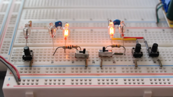
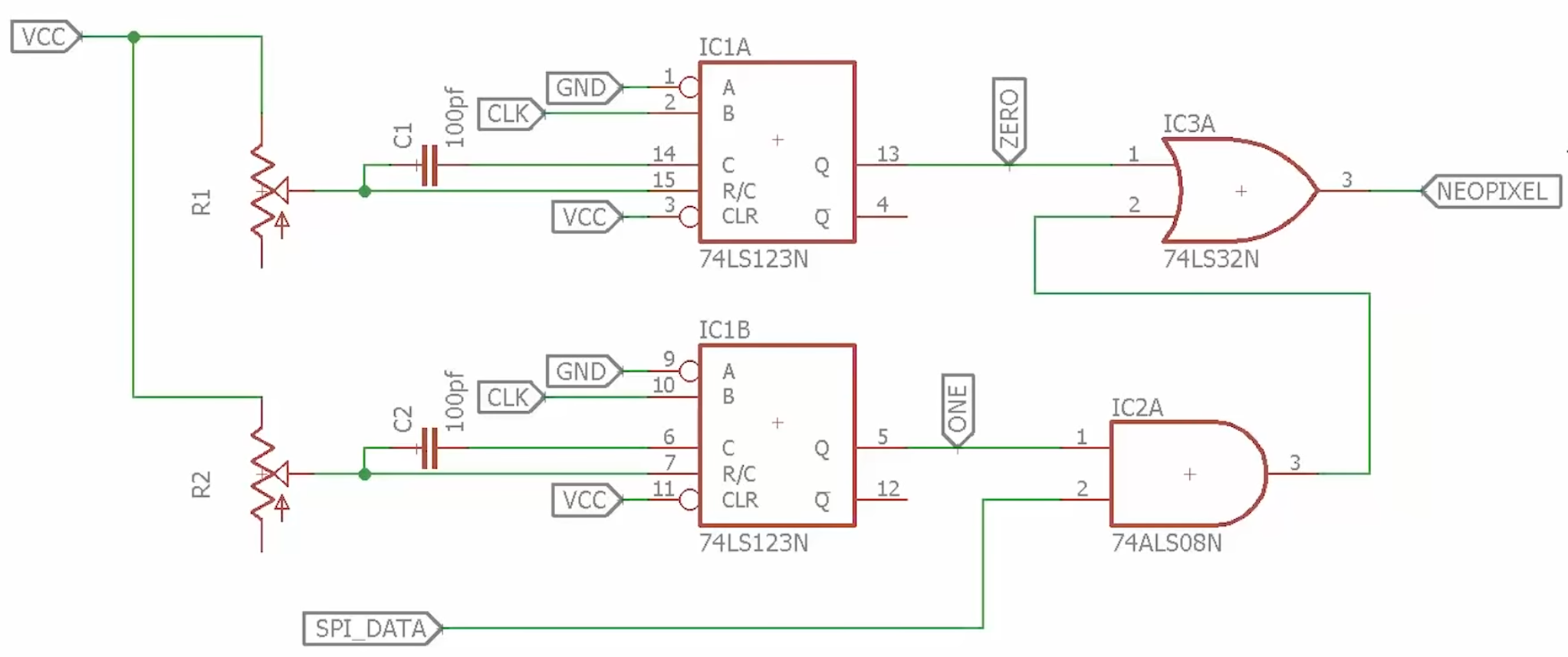
[Ben]’s solution uses some external hardware to reduce software requirements. The 74HC123 dual multi-vibrator is used to generate the two pulse lengths needed for the NeoPixels. The timing for each multi-vibrator is set by an external resistor and capacitor, which are chosen to meet the NeoPixel timing specifications.
The 74HC123s are clocked by the SPI clock signal, and the SPI data is fed into an AND gate with the long pulse. (In NeoPixel terms, a long pulse is a logical 1.) When the SPI data is 1, the long pulse is passed through to the NeoPixels. Otherwise, only the short pulse is passed through.
This solution only requires a 74HC123, an AND gate, and an OR gate. The total cost is well under a dollar. Anyone looking to drive NeoPixels with a resource-constrained microcontroller might want to give this design a try. It also serves as a reminder that some problems are better solved in hardware instead of software.
Heaven, for tech-inclined late-1970s British kids.
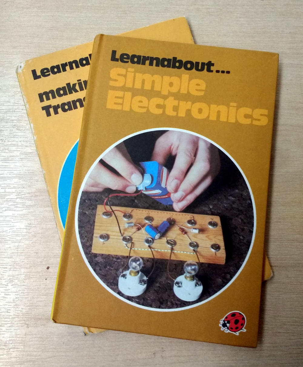
Early last spring, we featured a book review, as part of our occasional Books You Should Read series. Usually these are seminal tomes, those really useful books that stay with you for life and become well-thumbed, but in this case it was a children’s book. Making a Transistor Radio, by [George Dobbs, G3RJV], was a part of the long-running series of Ladybird books that educated, entertained, and enthralled mid-20th-century British kids, and its subject was the construction of a 3-transistor regenerative AM receiver. If you talk to a British electronic engineer of A Certain Age there is a good chance that this was the volume that first introduced them to their art, and they may even still have their prized radio somewhere.
Making a Transistor Radio was a success story, but what’s not so well-known is that there was a companion volume published a few years later in 1979. Simple Electronics was part of the imprint’s Learnabout series, and it took the basic premise of its predecessor away from the realm of radio into other transistor circuits. Transistor timers and multivibrators were covered, Morse code, and finally quite an ambitious project, an electronic organ.
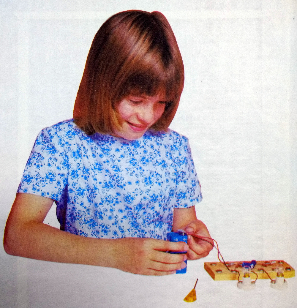
Opening the book it is evident that there has been a slight cultural shift since the first volume was published. The typography is much more modern in feel, and the picture of the child experimenter on the inside of the cover is a photograph of a late-70s young girl in place of the 1950s-style boy wearing a tie building the radio. The practical nature of the writing hasn’t changed though, while it states that some of the background information is not being repeated from Making a Transistor Radio we are taken straight into the deep end with a section on the tools required to work with the series’ signature screw cup on wooden baseboard construction technique.
Construction was so much easier when transistors came with long leads.
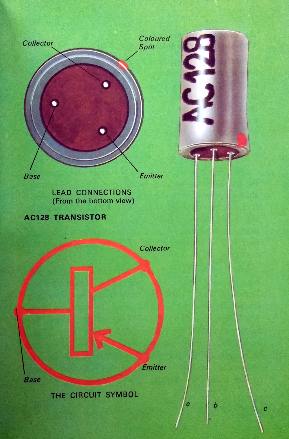
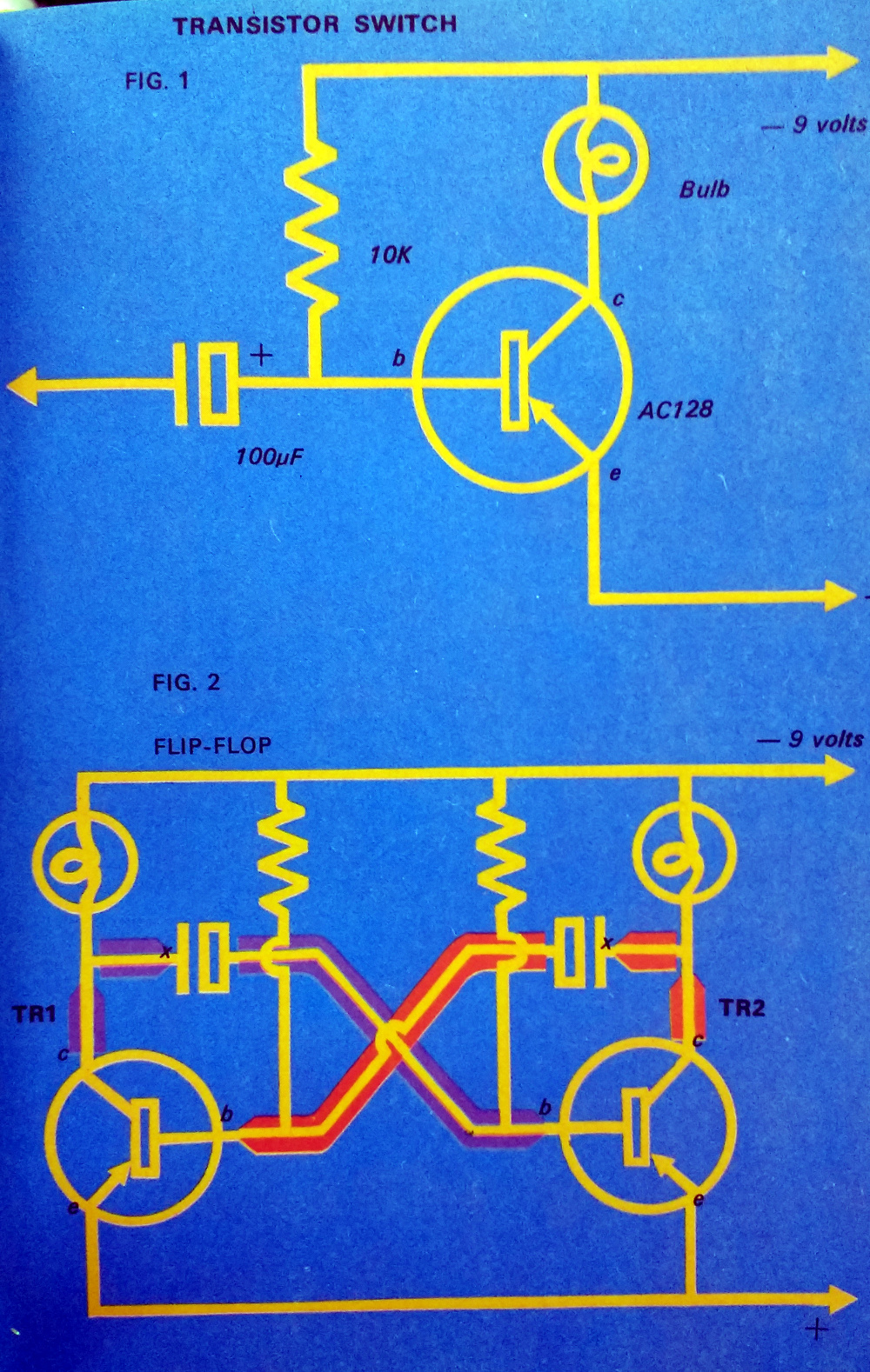
The original book used germanium transistors from the Mullard OC series, OC71s and an OC44. These were some of the earliest British transistors, and as I can attest from building my radio in that period, difficult to obtain by the late 1970s. This book has therefore moved on to a later design, the AC128. Still a germanium PNP device, but this time in a metal can and crucially still available at the time due to having been a part used in more than one mid-70s colour TV set. We’re given a no-nonsense introduction to the device, told about its package, pinout, and schematic diagram. It’s refreshing to see a children’s book in which the child is introduced to such an adult subject as this without being constantly reminded that they are a child.
We then spend a couple of pages looking at a transistor as a switch. A 10K base resistor is used to bias an AC128 with a flashlight bulb as its collector load, and with a flying lead to the negative supply (remember this is a PNP transistor!) the bulb can be turned on and off. In typical form, we’re shown how to make a bulb holder from a paper clip should we not be able to source a dedicated component. The basic switch is then extended with an electrolytic capacitor to make a simple time delay switch, and finally we’re shown how two such circuits combine to make an astable multivibrator and flash a pair of bulbs.
The astable multivibrator, explained for kids.
For me, circa 1979 or 1980, this was something of an earth-shattering moment. For the first time, I understood how an oscillator worked. That transistor turned on, triggering the other transistor after a delay, which in turn triggered the first transistor after a further delay, and so on and so on. It’s a simple enough circuit, but to a kid who had only recently been introduced to electronics, it was an amazing moment of revelation to have an insight into how it worked. It probably gave me a lifetime bad habit in that the two-transistor astable has become my go-to circuit when I need a quick and dirty square wave. They can be assembled from commonly desolderable scrap components on a bit of PCB or tinplate in a matter of minutes, and I have used them for nasty logic clocks, harmonic-rich signal sources, PWM oscillators, switching power supplies, and many more applications all because of this book.
Enough reminiscences, and time to turn the page. For a bit of fun we’re shown the light flasher as a robot with flashing eyes, before substituting some of the components and adding a crystal earpiece for an audio oscillator. This is the first part of the serious business of the book, because it forms the basis of all the following projects. It’s also the furthest I got with the book as a child, because of a lack of enough AC128s for the complete organ project, and a lack of aptitude for music. I was shown how to use a soldering iron, discovered that scrap TV sets in dumpsters contained a goldmine of parts, and never looked back.
[George Dobbs] is a radio amateur, so of course once he has a legion of British kids with audio oscillators he then leads them into making a Morse Code practice oscillator with a filter and a key made from tinplate. In typical no-nonsense style we’re introduced to amateur radio, code, and basic operating procedure. There are even instructions for making a two-station setup using three-core mains flex, how many kids who built that went on to have callsigns of their own?
The organ project awaits, but before then we have time for a couple more circuits to get used to varying the pitch of the oscillator. A “violin” using a potentiometer, and a photoelectric cell each get their own page, after which you have to wonder: how many kids managed to get their parents to shell out for that ORP12 CdS cell?
Never lose the fascination you gain from your first project!
The organ is of the “Stylophone” variety, with notes picked out using a stylus over conductive pads on the keyboard. Skeleton preset potentiometers are used for tuning, with the alternative of filing notches in carbon resistors. This would not have been a cheap project at all on a pocket-money budget in 1979, did any readers build it? If they went for the final two pages, the same 1-transistor loudspeaker amplifier as that used in the transistor radio, and a vibrato circuit using a low-frequency version of the multivibrator, then pocket money would have been in very short supply indeed.
But to look at it this way probably misses the point of the book. Where the previous book was all about presenting a single project in stages, this one is more about teaching some basic transistor circuits in stages. When I was given a copy I had a basic idea about transistors from those OC71s in the radio, but when I’d read this one and built some of the circuits I had a much more varied grasp of solid-state electronics. I knew about RC circuits and oscillators, and the effect of changing the values of an RC circuit on frequency. Some of the things I learned from this book I still use today, and nearly a decade after reading it when I was a 1st year electronic engineering undergraduate I hit the ground running in our course on transistor circuits because of it.
Learnabout Simple Electronics has been out of print for well over three decades now, but if you want a copy you should be able to find it in second-hand book stores online. There’s also at least one PDF version available too, if all you want is a quick look.
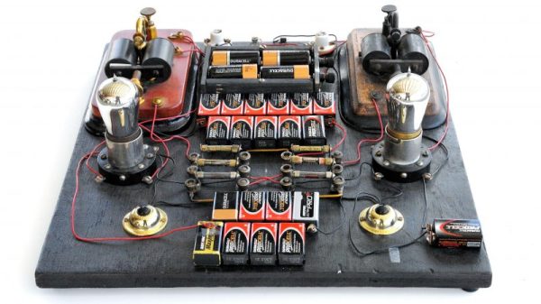
It’s easy to get caught up in the excitement of creation as we’re building our latest widget. By the same token, it’s sometimes difficult to fully appreciate just how old some of the circuits we use are. Even the simplest of projects might make use of elements that were once a mess on some physicist’s or engineer’s lab bench, with components screwed to literal breadboards and power supplied by banks of wet-cell batteries.
One such circuit turns 100 years old in June, which is surprising because it literally is the building block of every computer. It’s the flip-flop, and while its inventors likely couldn’t have imagined what they were starting, their innovation became the basic storage system for the ones and zeros of the digital age.
How many geeks does it take to flash a lightbulb? Judging from the list of entries in the 2017 Flashing Light Prize, so far only seven. But we suspect Hackaday readers can add to that total.
The goal is almost as simple as possible: build something that can flash an incandescent light bulb for at least five minutes. The system actually has to power the bulb’s filament, so no mechanical shutters are allowed. Other than that, the sky is the limit — any voltage, any wattage, any frequency and duty cycle, and any circuit. Some of the obvious circuits, like an RC network on a relay, have been tried. But we assume there will be points for style, in which case this sculptural cascading relay flasher might have a chance. Rube Goldberg mechanical approaches are encouraged, as in this motor, thread, stick and switch contraption. But our fave thus far is the 1000-watt bulb with solar cell feedback by Hackaday regular [mikeselectricstuff].
Get your entry in before August 1st and you’ll be on your way to glory and riches — if your definition of rich is the £200 prize. What the heck, your chances are great right now, and it’s enough for a few pints with your mates. Just don’t let it distract you from working on your 2017 Hackaday Prize entry — we’re currently in the “Wheels, Wings, and Walkers” phase, so maybe there’ll be a little crossover that you can leverage for your flasher.
[Ian Lee, Sr] wanted to have an educational activity at his younger son’s birthday party. These were uncharted waters for him as he doesn’t remember education taking place at his own early birthday parties. But he came up with a great idea, with was to teach soldering using interactive badges which each guest could assemble themselves. He needed about twenty, so he tried to keep the BOM as small as possible. But that didn’t mean skimping on features.
You can see the black LED-type package on the left of the assembled badge above. This is an IR receiver whose counterpart transmitter is on the right side of the board. When two of these get within 6-8″ of each other the start talking back and forth. There is no microcontroller involved, instead the system relies on a multivibrator design. One of the red LEDs at the corner of the ‘smile’ is always blinking. When it is off, the IR transmitter is powered. This is picked up by another badge’s receiver, which lights the second ‘smile’ LED. You can see this happen in the short clip after the break.
Although there are relatively few components that went into this, it would take the kids a long time to put them together as they’re just learning. [Ian] and his eldest son soldered on all of the components except for the resistors beforehand.
[Viktor] dredged up a hack he pulled off years ago. His grandfather likes to end the day in front of the TV, but he falls asleep soon after sitting down. Rather than tick away the electricity meter all night, [Viktor] built an automatic shutoff which is akin to a modern TV’s sleep feature.
At the time microcontrollers were not as easy to source as they are now. So [Viktor] used a circuit based on the 7400 family of logic chips. It uses a multivibrator to feed some binary counter chips. These are used to divide the oscillations to establish the desired timing. He tuned the system to be about 15 minutes, but that can be adjusted using a potentiometer built into the multivibrator. When time is about the run out an LED next to the TV comes on. This way if [Viktor’s] grandfather is still awake he can press a button next to his chair to reset the counter. But if he’s already snoozing the counter will eventually switch off the television.