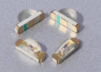
One of the most artistic applications of electrical engineering in recent memory is the burgeoning badgelife movement. This is an odd collective of people who are dedicating their time to rendering their own accomplishments in printed circuit boards. Of the entire badgelife collective, one of the most visible efforts are in Shitty Add-Ons, with a particular focus on reverse-mounted LEDs. Yes, you can install SMD LEDs upside down, and if you have your copper layers right, the light will shine through the badge.
One of the most prominent users of reverse mounted LEDs is [TwinkleTwinkie], and now finally we have a writeup on the science of reverse mounted LEDs. There’s a lot to unpack here, so buckle up and prepare to burn the tips of your fingers on a soldering iron.
For truly reverse-mounted PCBs, there are two options. The first, and most expensive, are ‘reverse gullwing’ LEDs. These LEDs are just like normal LEDs, except the SMD pads are reversed, allowing you to mount it so the light shines into the PCB. These LEDs are expensive, rare (only three companies make them), and they don’t really give off a lot of light. The other solution to reverse-mounting a LED is simply taking a standard 1206 SMD LED and manually soldering it upside-down. This is not pick and place friendly, although I’m sure you could find an LED manufacture that would put LEDs in reels upside-down if you want.

The takeaway for reverse mount LEDs is pick two: good, fast, or cheap. Reverse gullwing LEDs are expensive, but can be pick and placed and provide sufficient illumination. Hand-soldered LEDs installed upside down are cheap, slow, but also good.
But there is another option. Side view LEDs are a thing, and they can be pick and placed. You can get them in every color, and even UV. [Twinkle] has experimented with side-view LEDs in place of reverse mounted LEDs, and the results are promising. By putting the side view LED next to part of a PCB without copper or soldermask, there is some light bleed through the PCB. It’s somewhat uneven, but with a hot melt glue diffusor, you can get a somewhat decent bar of light being emitted through a PCB.
If you want to put blinky on a PCB, you have a lot of options. If you want to put blinky on a PCB without having any visible light source, these are your options. This is the state of the art in artistic PCBs, and we’re so glad [Twinkle] could share it with us.


This “artistic application” also works on non-badges ;)
https://hackaday.io/project/162980-you-are-here
(shameless self-plug)
Now I want to make a PCB map of a convention area. Then, use reverse-mounted LEDs to point out where you are. A really silly idea, but maybe something worth trying one day.
That’s cool and all, and for single badges perhaps worth it, but I’d bet that it would be cheaper in quantity to use standard LEDs the correct way up, and mount a second pcb (or other diffuser) on top.
Exactly what I ended up doing for my pcb word clock (https://hackaday.io/project/164406-small-word-clock). Early on in the design I did think of reverse mounting the LEDs on the backside of the front letter mask, but it was apparent that light bleed would be a bigger problem than back lighting them from a second board with a 3d printed light divider to prevent bleed.
I thought you did a great job with that project. Good engineering within a clean artistic design. :D
Looks very pretty, nice job!
LED manufacture*r (spelling)
> One of the most artistic applications of electrical engineering in recent memory is the burgeoning badgelife movement.
[citation needed]
How fortuitous! I was actually considering reverse mounted LEDs for a motorcycle dashboard just yesterday! Looks like some of the experimentation and hard work has been done for me! Thank you [TwinkleTwinkie]!
I read too much sci-fi. I read badgelife as badlife.
In old Nokia GSM phones you had 1206 LEDs reverse mounted, which shined through a hole (plated) in the PCB for the illumination of the keypad and LCD. When I replaced the ordinary green LEDs with the then-new blue ones, I had only 0603 parts available. And after (partially destructive) removal of the old ones I noticed, that the small new ones fell right through this holes with nothing to solder to. :-( It took about 4 hours of work under the microscope to mount them with tiny pieces of wire, each one 1mm long.
Another area where reverse-mount LEDs are incredibly useful (having used the RGB ones from Wurth myself) is when performing PCB assembly as it can allow you to keep all your components on a single side whilst still allowing easy viewing of your LEDs (which saves not only cost on having your board run through the pick’n’place twice but also no need to do reflow on both sides). Okay, it may be less of a concern if you’re building one-offs in your office but important to think about when considering DFM.
pretty easy to source reverse mount 3528 RGBs. We are using loads in our keyboard.
Hi Matt, my company is a manufacturer of 3528 RGB reverse mount. I’d like to send you information about it.
Nice article. How about an article describing the steps to take in KiCad to properly create a PCB in order to have reverse mounted LEDs shine through?
A couple of times it’s mentioned “(only three companies make them)” w/r/t reverse-mount gullwing LCDs. I’ve used the ones from SunLED (google “XZVG45WT-9” and/or “XZMDKCBDDG45S-9”), and “the RGB ones from Wurth” are mentioned above (but I can’t find a precise link). Frances Wei mentioned harvatek.com (again I can’t find a link), and Kingbright seems to make some (eg “AA3528QBS/D09”). What are some other sources? Anything suitable for PCBA from JLCPCB?