
It is hard to imagine a time without active amplification. However, if you go back far enough, radio communications started in an era where generating RF required something like a spark gap and reception was only possible if the signal was strong enough at the antenna — like with a crystal radio. It would be a few years before tubes allowed both transmitted and receiving signals to be electronically amplified and longer still before transistors that would work at radio frequency appeared. However, even active devices have had their limitations and the parametric oscillator and amplifier are ways around some of those problems.
These were more popular in the 1970s when it was harder to get transistors that would work at very high frequencies. They are still useful when you need very low noise amplification. In addition, the same effect is used in optical devices and you can even observe the effect in mechanical devices.
What Is It Exactly?
The phrase parametric means that the amplification or oscillation occurs because of the change in a parameter of the system. A simple example would be a variable capacitor. We know the charge in a capacitor is equal to the capacitance times the voltage across the unit. That also implies that, if charge is known, we can know the voltage by dividing the charge by the capacitance. To put it in numerical terms, if a 0.1 farad capacitor has 12V across it, the charge is 1.2 coulombs. Suppose our input signal is 12V and we let the capacitor charge up to that value. Then we twist the capacitor’s knob to give it a value of 0.05 farad. The charge can’t change, so now we have 24 volts across the capacitor. That’s an amplification of 2 times. These values, of course, are not practical. Nor is it practical to twist a capacitor knob constantly to amplify. However, it is a good analog of how a parametric amplifier works.
In Practice
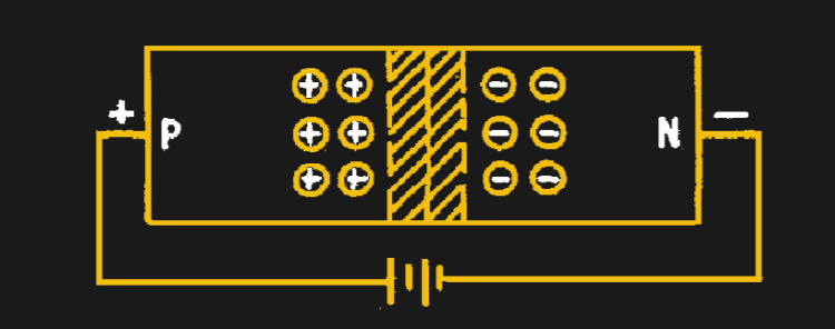
In a real circuit, the parameter often is capacitance — although it doesn’t have to be — but instead of using a mechanically variable capacitor, a varactor provides the varying capacitance. If you haven’t done much with varactors, the idea is simple. When a diode is reverse biased, there is a small insulating gap between anode and cathode (see figure below). That means a reversed diode has capacitance. In general, the higher the reverse voltage, the wider the gap which changes the capacitance. Varactors are diodes optimized to take advantage of this effect.
The varactor parametric amplifier, then, has two inputs: the incoming signal and a locally-generated signal that varies the varactor’s parameters — the pump frequency. For things to work, the pump frequency should be at least twice the input frequency. A typical arrangement will have three different tuned circuits. One tuned for the input frequency, one tuned for the pump frequency, and one tuned for the desired output frequency.
Since the input signal is going to cross modulate with the pump frequency, it isn’t surprising the amplifier also acts as a mixer. This makes it a great converter as seen in this excellent project by [Electronic Projects for Fun]. In this design, a 7 MHz signal is fed into a pair of varactors pumped with a 66 MHz pump. The output is then filtered to get a 73 MHz output signal. Of course, you also get a difference frequency and some of the fundamentals, but the filtering will select those out.
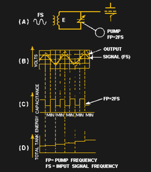 If you dig into the math, you’ll find there are two ways to treat a parametric amplifier. The degenerate case is where the pump frequency is exactly twice the input frequency. The non-degenerate case covers when the pump frequency is not. The operation is similar, but the governing math and the resulting gains are different. Usually, it is easier to understand how the system works in the degenerate case, but more practical to build a non-degenerate system. If you ever do see a degenerate system, however, it usually won’t have the tuned circuit for the desired output frequency (sometimes known as an idler).
The degenerate case is simpler to understand since the pump frequency occurs twice per full cycle, adding energy to the system and tracking the input (shown in this figure). The non-degenerate case works in a similar way but is less critical for alignment of phase. It does, however, need more circuitry.
History
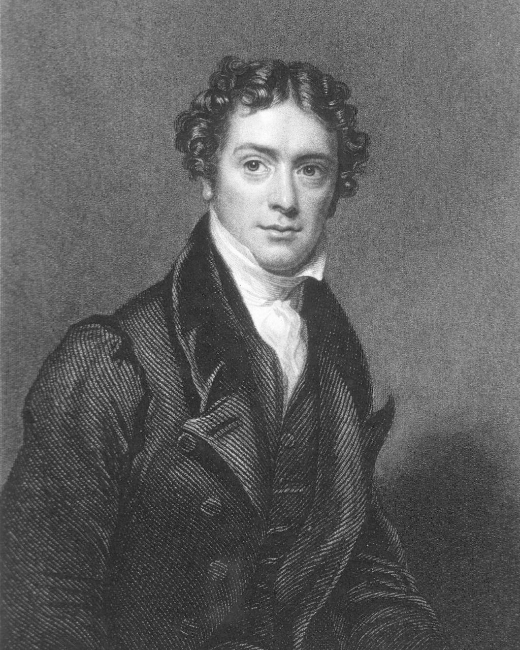 Michael Faraday was the first person to report how oscillations of one frequency could be amplified by a signal at double the frequency while studying ringing wine glasses in 1831. It would be 1892 before Geroge Francis FitzGerald applied the idea to electric circuits.
Those early experiments didn’t use a varactor, of course. They used a dynamo and varying inductors. In the early 1900s, paramps — another name for a parametric amplifier — found use in low-frequency radio transmission systems, employing iron-core inductors as the reactive element.
It was 1956 when the varactor appeared and, unlike the inductors previously used, they could support frequencies considered to be in the microwave region. Marion Hines at Western Electric used the new device to create a microwave amplifier.
Speaking of history, we talked about Rufus P. Turner, the prolific solid state pioneer. He wrote a book about varactors that you can find online.
Advantages
Because the paramp varies a reactance instead of a resistance, it avoids several common sources of noise introduced by tubes or transistors. This has made the amplifier useful for things like radar and space-related radio like radio telescopes and satellite receivers. Special design techniques — bridge circuits and cooling — can allow the circuit to reach very low noise figures.
The fact that the amplifier also acts as a mixer can be an advantage in things like receiver design where you were planning on generating an intermediate frequency anyway. Another advantage is that the paramp doesn’t require a direct power supply. All the energy comes from the pump oscillator (and, of course, a little from the input signal). Presumably, the pump oscillator will require power.
Today
Increased availability of transistors that can operate at very high frequencies has made the parametric amplifier less common unless there’s a severe low noise requirement. Perhaps because of the diminished importance, a lot of what you can find to read on the subject is pretty old. In fact, one of the best practical articles is from the Navy’s NEETS program, which is where most of the figures in this post came from.
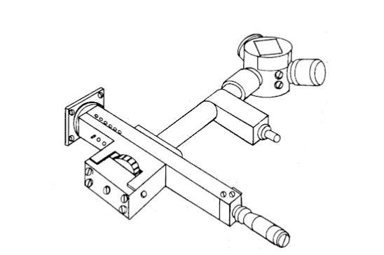 If you hang around hamfests or surplus stores, you might even find a parametric amplifier module. They are often for microwave frequencies, so they’ll probably be attached to waveguides like the one below.
Varactors show up in lots of other places too. FM modulators, VXOs (a crystal oscillator you can tune slightly), PLL voltage controlled oscillators (VCOs) and tracking filters all often use varactors. If you want to experiment yourself, you can pick them up relatively inexpensively. However, the truth is, all diodes exhibit this effect. It is just most pronounced and useful (and documented) in diodes meant for this service.


A varactor is most commonly used as a variable capacitance, not as a parametric amplifier, often requiring more than one in parallel for higher total capacitance. Where I worked, they were also used to phase shift RF amplifiers.
So, how about a Tunnel (Esaki) diode article? They can be used as high frequency oscillators, as they effectively have gain (via a negative resistance region of their transfer curves).
Sam Harris is credited with the first practical parametric amplifier, writing for hams in CQ magazine about 1958. I don’t know if that’s true, but I’ve recently read the patent innthe company name, I think Microwave Associate.
But varactors were relatively new at the time. So he talked about them, and urged people to try other devices to get going, and seemed to hint that when someone needed a good one, ie ready for a full blown parametruc amplifier, he could probably supply a varactor.
Ever since , people have used other diodes as varactors, trying what they have before spending a lot of money (though obviously things like varactors with high max to min capacitance are less likely to come from random junctions.
Michael
Very interesting, thank you!
:o)
Do magnetic amplifiers next! :)
Interesting… I’ve been wondering about generating and more-so detecting microwaves from 6GHz and really now days 26GHz on up to the Terahertz range. Seems that’s where the electromagnetic optics characteristics of the phenomena kick in more-so and waveguide detectors start showing up and diode detectors aren’t so common.
I’m newbie to microwaves; so definitely a write up on Gunn diodes, Tunnel diodes, TWT’s, BWO’s and gyrotrons would be great each in themselves.
Great article after reading through the second and third time.
I’m thinking like a MOSFET vs a BJT… though seems I’m thinking diode and transistor analogy and wondering inductor and transformer somehow analogy. I have to read into the math more.
This will be a neat project to perform with the DUT and a signal generator, oscilloscope and spectrum analyzer.
Left me now wondering about the inductive method that is equivalent even though isn’t relevant with higher frequency work much if at all? Thanks for sharing!
The tuning capacitors in old radios were built with a stack of plates, half fixed, and half on a rotationg shaft, with an air gap between them. They can be used to demonstrate this capacitance-voltage effect that was mentioned.
Connect the capacitor to a source of DC voltage through a high value resistor (like 1 megohm). Obviously, the capacitor charges to that voltage. Now spin the capacitor with your fingers (or a small motor, if your capacitor does not have end stops). Look at the voltage across the capacitor with an oscilloscope, and VOILA! There is a substantial AC voltage, several times the DC voltage.
This phenomenon was used to make “infinite” voltage multipliers for high voltage experiments. At maximum capacitance, the fixed caps charged the variable cap. At minimum capacitance, the higher voltage charged the fixed caps. The voltage ratchets up until the diodes break down or something arced over!
It is right if this phenomenon is not constrained by negative resistance feedback.
In that case the maximum energy equal that of pumping, whereas voltage amplitude is limited to the Manley-Rowe laws.
Thank You for an outstanding article. I am retired now, but early in my career I worked with a Ka-band satellite system that used parametric amplifiers. I have never understood the crux of how these work until now. Well Done!