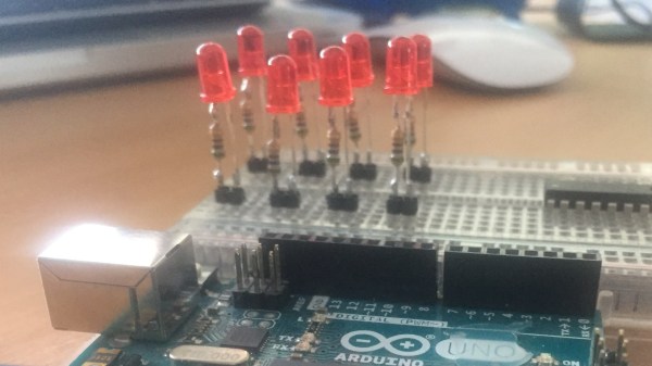
Sometimes the most useful hacks are also the simplest ones. A case in point is the LED and resistor assembly that [Skippy] recently posted on his blog. The idea is to solder up some pre-made indicators with integrated resistors to save space on the breadboard when prototyping — instead of four slots, you only use two per LED. This is about as easy a trick as you can imagine, but it has the hallmark of a classic hack: a high utility-to-work ratio.
The deluxe assembly uses a two-pin header as a base to plug into the breadboard. This, of course, could be optional since some breadboards have a memory for the widest pin previously inserted — using header pins may eventually make the slots a little flaky for smaller component leads. But, if you’re mostly using header pins in the breadboard anyway, this is a good way to avoid kinking the leads.
While there are LEDs available with integrated dropping resistors, building your own means you can use whatever LEDs you prefer — or simply have on hand — and adjust the resistor value for different voltages or to adjust the brightness. And for those of you who plug in LEDs without current-limiting resistors, we’re going to assume that you’ve thoroughly researched whatever is driving them and done the math to ensure they’re safe. Or not: they’re your LEDs after all.
We previously featured a no-solder breadboarding trick for SMD LEDs. What’s your favorite solderless breadboard hack? Let us know in the comments below.
Thanks to [Roboteernat] for the tip!


