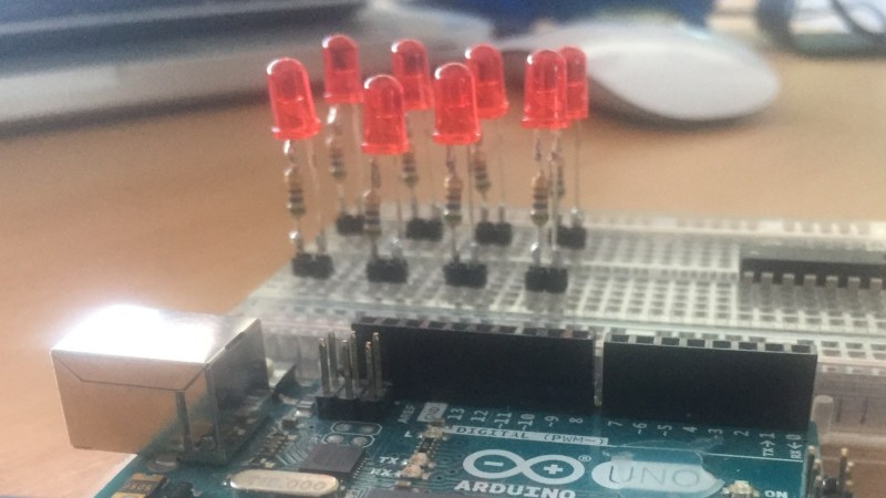
Sometimes the most useful hacks are also the simplest ones. A case in point is the LED and resistor assembly that [Skippy] recently posted on his blog. The idea is to solder up some pre-made indicators with integrated resistors to save space on the breadboard when prototyping — instead of four slots, you only use two per LED. This is about as easy a trick as you can imagine, but it has the hallmark of a classic hack: a high utility-to-work ratio.
The deluxe assembly uses a two-pin header as a base to plug into the breadboard. This, of course, could be optional since some breadboards have a memory for the widest pin previously inserted — using header pins may eventually make the slots a little flaky for smaller component leads. But, if you’re mostly using header pins in the breadboard anyway, this is a good way to avoid kinking the leads.
While there are LEDs available with integrated dropping resistors, building your own means you can use whatever LEDs you prefer — or simply have on hand — and adjust the resistor value for different voltages or to adjust the brightness. And for those of you who plug in LEDs without current-limiting resistors, we’re going to assume that you’ve thoroughly researched whatever is driving them and done the math to ensure they’re safe. Or not: they’re your LEDs after all.
We previously featured a no-solder breadboarding trick for SMD LEDs. What’s your favorite solderless breadboard hack? Let us know in the comments below.
Thanks to [Roboteernat] for the tip!


seriously… the big “hack” here is “soldering parts onto a solderless breadboard”
If this catches on then soon people will be plugging in completely soldered circuits and modules onto the solderless breadboard. Then soon after that people start “discovering” alligator clips and find out that you don’t even need a solderless breadboard any more or the “find out” that you “can” solder things directly to other things. Or that you can tie things together with paperclips (which actually is a hack many of us grew up with).
I wonder how long it takes before people “discover” that you can solder two LED’s anti-parallel and if you use a red and a green one and stick them into a ping-pong ball you get your own bi-color LED. And you can make it even brighter by leaving out the resistor.
Geez I bet you’re fun at parties. Like it or not it’s a pretty neat & simple way to keep the breadboard clean. Sometimes little tricks like this are necessary. I’ve even jammed parts of a circuit into those blank DIP package housings to use as mini “modules” to help keep things clean. I’ve also done something similar to this guy using regular DIP sockets to create a “bank” of components that need an integrated resistor/cap/etc. You could just stick it right in the breadboard but it wouldn’t be mechanically robust enough to take it out & put it back more than a few times.
hello?.. I’m 10 years old. grow up with your hacks and I’ll grow up with mine.
”’seriously… the big “hack” here is “soldering parts onto a solderless breadboard””’
No!
The biggest hack is to call this a hack!
:-Þ
and will discover that you can buy leds with internal resistor
Paragraph 3 ruined that for them as welll!!
“seriously… the big “hack” here is “soldering parts onto a solderless breadboard””
It’s not that. So you didn’t understand the article. Should you have commented anyway? It’s not for me to say but clearly the answer is NO. There’s no “soldering parts onto a solderless breadboard” anywhere in the article.
Epic fail.
Okay you’ve got me there.
I’m fully ware of the parts not being soldered onto the breadboard directly or using the breadboard as a stand that holds the header during the soldering action. What I mean is that this “hack” (because by the readers here it is expected to be a hack, otherwise why would it be on HACKaday) does require some soldering. Unless you can buy these pre-soldered from ebay aliexpress or wherever. Soldering is perhaps one of the things you try to avoid when using a breadboard. And really what is the gain, because in many cases you’ll have to admit, the 2-pin header has the pins to close to each other to fit for all possible situations you’ll encounter on a breadboard. So you’ll have to add another wire. While with the single LED and the single resistor you can already achieve the same result out of the box/bag/strip. And if you worry about using an extra hole for the LED resistor connection, you can always twist the resistor wire to with the LED wire.
What’s next, a header on a switch or a header on a potentiometer perhaps a header on a banana jack so you can easily connect to your multimeter. A simple 2-pin header for an SMD decoupling capacitor that didn’t have leads to cram it into the breadboard. Also used the SMD to DIL adapterboards to be able to place a certain SMD-only opamp onto the board. Then some headers on a display… oh wait some (like the 0.96″ oled) already have this. I don’t like breadboards but when I did needed to use them (because my boss insisted for a certain project to “save” time) those were the first things I made. Because they are obvious.
Any way… regarding “epic fail”, I wouldn’t use this here, really, that’s not appropriate.
But don’t get me wrong, I’m not attacking the “maker” because I’m sure that for that person it is most certainly practical. I’m trying to make a statement regarding the hackaday author of the article as there are some many really brilliant/artistic/beautiful projects around that they shouldn’t be concentrating on a LED+resistor on a stick.
I’ve been using this trick for ages. But you should drop the pin header, it’s completely unnecessary, it damages the breadboard (as mentioned) and it also constrains the LED to two adjacent holes. Most of the time you would need the LED cathode on the ground rail, so it’s essential that you can bend the two leads to connect them.
What I do is add a resistor to the Red Anode of a bidirectional LED so it works both ways, Red = +ve on the resistor, Green = -Ve on the resistor. It just makes it a little bit handier.
+1 for this. I have a stack of these pre-made and I just jam them into the breadboard as needed. It’s often nice to be able to pick red/green as I go to make debug stuff easier
I’ve been doing this for years. Just sort of assumed it was a standard thing to have laying around. First time I made one I felt pretty dumb for never having done it before.
Only difference is I don’t use the 0.1″ header so I’m not constrained to using adjacent holes. Does that make me some kind of genius?
Yep. I think I have one lying right here ….
But it is worth pointing out so people can slap their forehead with their palm, and say, “oh, yeah!”
The pin headers defeat the purpose, since you’re probably going to be connecting one side of the LED to V+ or GND. With the header constraining things to adjacent holes, that requires a separate wire that could just as easily be a resistor.
I agree. These are very practical but only as long as one of the legs can reach the power rails. A resistor with a thicker connector is ideal as the thin ones are hard to use on some breadboards.
I still have some of these laying around that I hooked up in school thirty years ago.
OK, I’ll be the first to say it. For years I’ve been using the resistor to connect to ground, which always comes loose as I wiggle and move stuff, then have to trouble shoot— this, I never even thought of. Yeah, it might damage the breadboard if you use too big of headers. But ,realistically that “memory” the article mentions is a polite way to say crap breadboard– and if you are using crap breadboards, they are cheap enough that you really don’t care because you buy them by the dozen and wait 6 to 8 weeks for them to arrive.
So +1 to this hack. It cleans up the breadboard and lets you focus on bigger issues.
Headers with a space (or 2+ depending on the power bus and the breadboard) between pins so that they could straddle both the power bus and a regular connection point would make this technique more helpful.
Great idea!
How to hook up 8 LED cleanly at a time WITHOUT soldering and mess of wires:
LED Bargraph, plug SIP resistor network (current limiting resistor) on one side of the bargraph, connect the common pin in SIP to Gnd or Vcc depending on your need.
Anything else is uncivilized.
FYI: SIP resistor network for those who haven’t seen one
http://4.bp.blogspot.com/-4eBtjh7z-DM/Ve3aG3s10BI/AAAAAAAAPhE/6-4qHXCRQus/s1600/ResistorNetwork.gif
Found one example:
https://softsolder.files.wordpress.com/2012/11/dsc07514-led-bargraph-display-breadboard.jpg
You can buy through hole leds with a series resistor built in quite cheaply too e.g. Kingbright L-7113ID-5V
or you could just use the resistor to connect to ground, that way you don’t need an extra wire. Benefits of this approach:
* It takes less space,
* is less messy,
* is faster
* you don’t wear out you board as fast.
* you don’t need to solder to use your solderless breadboard
But the posted way sure *looks* nice
What is the difference between a hack and common sense…?
?? Spelling ??
I’ve also used self soldered modules for breadboards.
Some examples:
– ULN2803 + 8 resistors & LED’s for indicating purpose.
– Power MOSfet’s with TVS between Gate and Source.
– uC’s with the decoupling caps soldered on top.
– TO220’s on a small heatsink and their legs twisted 90 Degrees for easier insertion.
– Wallwart power supllies with a 2×5 pin from a dual header as power connector.
– 5 pin single row header with all pins soldered together to have a “Star ground”.
– Solder a piece of thick solid wire on top of the “star Ground” for attachment of the GND clips of scopes etc.
– Potentiometers and buttons with extra (unconnected) pins just for mechanical stability.
– Using pieces of perfboard as adapters to fit parts that otherwise would not fit on the BB.
Yeah, this is somewhat obvious. And for debugging nothing better than a serial port. It is probably available on every µC, if not you can do it in software and if your µC is not really small you can just use printf like on a PC. Of course it won’t work if you have really time critical stuff to debug, but than some LEDs are not really usefull either (humain eye is slow). Just invest 10$ in a simple logic analyzer (if 24MHz is enough for you) and download sigrok.
LA is different from some simple LED’s in that the LED’s can give real-time feedback of slow events without having to add external stuf with an USB cable to your PC.
(This is of course a smaller issue if you use the 5V from USB to power your breadboard)
But the EUR7 LA’s from Ali / Ebay / China are excellent tools indeed in combination with sigrok.
https://sigrok.org/
Some time ago I made a mini tutorial on how I use such a LA for debugging software on AVRfreaks:
https://www.avrfreaks.net/comment/2421756#comment-2421756
Digikey has (or had, I have a large box) LEDs with internal resistors. I get the 12v version – they are a bit dim at 3 or 5v but still visible. I have red, green and yellow. I don’t need to solder.
This looks similar to the parts I use:
https://www.digikey.com/product-detail/en/lumex-opto-components-inc/SSL-LX3044YD-12V/67-1079-ND/270877
The fixed 0.1″ spacing means you have to plug in this device in a clear area of board, then run 2 jumpers to it…3 total things need to be placed with 2 pins each.
The tradional way, string the LED between 1 desired point and a clear area of board and then the resistor from the clear area of board is 2 total things with 2 pins each. This “hack” is 50% more effort to use than the tradional method after you’ve gone to the trouble of soldering it together.
I prefer the little modules you can buy with 8 SMD LEDs pre-soldered in a row, it plugs into the breadboard so that it spans the ground rail and brings 8 pins to 8 rows of broadboard to drive the LEDs.
Geez you people are harsh. I sense a lot of “if it isn’t my idea, it’s a bad idea” in these replies.
Or “It was my idea but now someone else has thought of it and I’m no longer special”.
My spoon is too big!
Seems we forget that there are always new beginners… and they NEED to be exposed to such construction techniques. True, this is a “see it once and never forget it” type of hack… but there are new beginners just getting started up every day. Those new kids on the block would benefit a great deal from learning a few dozen of this type of construction technique on day one instead of figuring it out themselves some long while later. Posting it is a great service to the future of the community.
I wonder how much overlap there is between those who bitch that this is too simple and those who bitch when a beginner uses an arduino.
Why LEDs are not manufactured to include built in resistor?
Because the required resistor value depends on the application, and it would be too expensive to manufacture & stock all of the common combinations.
Thanks for the idea! Here’s my version:
https://hackaday.io/project/166013-breadboard-led
“and adjust the resistor value… to adjust the brightness”
Tsk, tsk. There’s a fail waiting to happen.
Oh, sorry—you meant adjust the 𝘸𝘢𝘷𝘦𝘭𝘦𝘯𝘨𝘵𝘩. Or was it magic smoke emission? Now you’ve got me confused.