Stepper motors are great for projects that require accurate control of motion. 3D printers, CNC machines and plotters are often built using these useful devices. [InventorArtist] built a stepper-based cycloid drawing machine, and made use of a nifty little hack along the way.
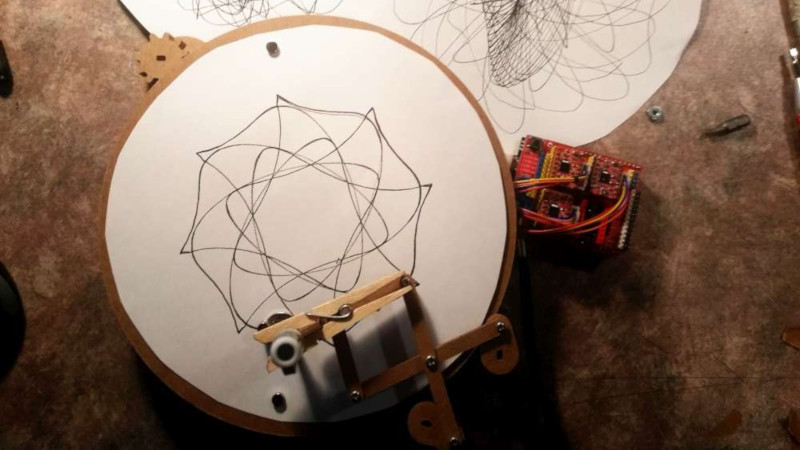
 The machine uses a rotating turntable to spin a piece of drawing paper. A pen is then placed in a pantograph mechanism, controlled by another two stepper motors. The build uses the common 28BYJ-48 motor, which are a unipolar, 5-wire design. A common hack is to open these motors up and cut a trace in order to convert them to bipolar operation, netting more torque at the expense of being more complex to drive. [InventorArtist] worked in collaboration with [Doug Commons], who had the idea of instead simply drilling a hole through the case of the motor to cut the trace. This saves opening the motor, and makes the conversion a snap.
[InventorArtist] was able to create a machine capable of beautiful spirograph drawings, and develop a useful hack along the way. Reports are that a jig is in development to make the process foolproof for those keen to mod their own motors. We expect to see parts up on Thingiverse any day now. We’ve also covered the basic version of this hack before.
[Thanks to Darcy Whyte for the tip!]


First :Love the project. Mathematical beauty. Can watch that all day.
Griping:
Just have to pop the little plastic cap on 28byj-48. Not real comfortable just drilling away in the blind. Design hasnt change in at least a decade but any of several could change it up in manufacturing. Noted before that some have their phase wires reversed at the motor. A4988 three Axis boards so wonderfully cheap now with an UNO to go. Some NANO. Package deal round <20$. Not really getting it as need for more torque nor accuracy that the bipolar conversion/A4988 can provide but need for simplistic cheap driving and a plethora of software available on a distinct platform made popular by 3D printing hardware(and software). Takes less time in assembly/wiring too than a uln2003 array of boards (unipolar).
After you drill a couple (then verify by taking apart) you’ll eventually get over it and just drill and plug. :) :) :)
So your plan is cut first and ‘ass’ess damage after? Snicker. That’s about right.
Have become Fairly proficient at popping the little blue cap with flat blade screwdriver and swipe pcb trace with box cutting blade or exacto knife. No need to disassemble shaft out bearing plate. Snap blue back in. No filling, tape, or ugly hole. I Also write bipolar on all three sides.
Those with less steady sure hands should probably use bench vise and rotary tool to cut trace. Otherwise Superglue is also good substitute for stitches. Is what it was design for.
I think the hole is nice. You can tell which motors are hacked and which aren’t.
Since when is this a beauty contest? :)
Don’t you love when you get to the comments and someone has already put to words your thoughts while reading the article?
However, sometimes the challenge is to build with what is already on hand, easily attained or what you already know. I’ve been accused of doing things the hard way due to junkyard habits. I my mind it’s the difference between hacking and assembling.
Profumple might have thought that too but needed a coffee break before finishing the comment. At least finish my thought before you hit submit…
That’s pretty much how I view hacking. The internet made it a lot easier to get parts, materials, tools, and the knowledge to build a lot of things, but hacking is more about using what you already have, or can get locally. Some things are still expensive, and hard to get, nor does everyone have room to house every tool and machine they want. Unfortunately, most people with ideas, don’t have access to the tools, parts and materials that fit their ideas, and have to figure out how to make it happen. Part of the fun and challenge. Even when you buy everything, they don’t always fit together as planned. Me, I’m basically cheap, and rather do projects, that will cost little or nothing to build. Doesn’t always work out that way, but I can get close enough to see if it’s worth spending the money on. Buying everything off the shelf, is sort of like building a kit, still some challenges, potential for learning a few new things in the process, but not as much fun as hacking something together.
Excuse to have more bean withstanding I dont believe this to be a scrap build (material on hand) and clearly some elegant details support hypothesis. The careful choice of pantograph style actuator and wooden gear drive on polar table for instance. An XY table would have been cheaper and could lose a gearhead motor and rotary table but wouldnt have been as beautiful nor graceful. Takes a little more processing power too for XY.
Thanks for the note.
This was built as part of the hack613 challenge to make a CNCish machine in under 10 or 20 bucks.
This one came out to about 18 dollars.
This one didn’t come out very Cartesiany though…
I like it for it Not being Cartesiany. Is good work.
I was thinking: Hmm, it should be easy enough to write a program to draw stuff like this on the screen. Then I thought a little more and realized that I have no idea how one would easily go about that these days. There are so many options, and I’m only familiar with the old, difficult ones. What’s an easy way?
On Windows with C++ or C#, GDI+ drawing to a bitmap and rendering that bitmap to the screen. Not super fast, but fast enough for this and really easy too. If you want to be in a browser, JavaScript makes it easy with the HTML5 canvas.
That said, it might not be necessary. You can derive the trajectory mathematically so you could write it out as an SVG file.
with a friction rather than a toothed drive, you might be able to achieve a non integer ratio, allowing for a more complete i.e. surjective, vs discrete, mapping of spirals onto the vector space that is the paper disc.
Yeah, I think it could be slightly more organic if it were a belt drive or friction drive. If it were easier I’d have probably done that. But the lazy susan bearing has a lot of play. A belt or friction would just add force…
Any ideas what to add to the motor? Perhaps a wheel machined from a hockey puck to run against the rotary table?
That might be an angle…
I just published the bill of materials for this thing in the article in case anybody wants to have a go at it. I’ll even publish the sketchup files if anybody wants them…
a rubber door stop, adhesive backed rubber chair leg pad of the right diameter, or section of bike tyre stretched onto a suitable dowel would probably do
While you’re here, check out [inventorartist]’s other drawing machines. I really like some of the ones with scissor/pantograph mechanisms!
What an amazing idea! I have a Thingiverse file that would work great for anyone wanting to 3d print their own. It is, of course, available to adapt to whatever use you’d like!
http://www.thingiverse.com/thing:3517417