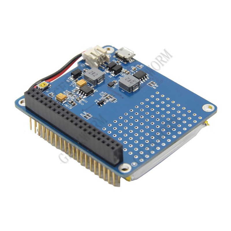
An uninterruptible power supply (UPS) isn’t something solely to have hooked up to your desktop PC. Your Raspberry Pi SBC might also benefit from it. Yet the available options aren’t too great, or are too expensive. This leads folk including [Joachim Baumann] to modify cheerfully cheap Chinese UPS HAT boards such as the Geekworm UPS HAT to fix its myriad of issues and missing features.
Inspired by a number of other hacks on this board which fixed things like needing to push a button on the UPS to boot the Raspberry Pi, [Joachim] set out to make a similar ATtiny-based solution that would address all issues, above all the fact that this Geekworm UPS does not detect when the connected SBC has turned off and will happily run the lithium battery pack dry. Finding a blog post by Simon who had reverse-engineered the board previously was immensely helpful.
With [Simon]’s project, a PIC MCU was used to provide a supervisor for the UPS HAT. It also bypasses the HAT’s control over whether the Raspberry Pi gets power or not. The results did however not fit [Joachim]’s needs, so the ATtiny Daemon project was born. This uses some of the fixes [Simon] implemented and adds a daemon that runs on the Raspberry Pi to establish two-way communications between the UPS and OS.
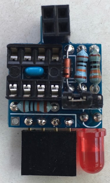
The settings for the UPS are stored also on the HAT, in the MCU’s EEPROM, with the daemon able to update and read it out as needed. The completed system provides a whole list of new features, as listed on the above linked Github project page. Probably most important are thresholds for warning, hard shutdowns and restart. The entire add-on board is also laid out to use only through-hole components, making it very easy for even novices to assemble.


I use an Adafruit Powerboost 1000 Charger with a Li ion battery for my Rpi working as VPN server.
Does the job pretty well!
I use a Stin jolt box 3.0 10,000 mah power bank for battery power and ups use on my Pi laptop/fpv ground station. It allows pass through charging and supplies plenty of amps (3.1a) for what I’m doing. Of course it doesn’t shut down the pi when power is lost, still have to do that yourself. I got 5400mah of 3s lipo powering monitor and fpv gear and the jolt box keeps up with that, haven’t had pi lose power before lipos. Was going to add 5 volt to keep jolt box charged but felt it didn’t need it. Record my FPV to Pi with Luvc and one of those otg fpv receivers.
The Powerboost on its own does not provide any UPS functionality, but you could easily use the ATTinyDaemon to change that. Simply build it on a breadboard, connect the Powerboost EN pin to its GW-SW pin (pin 6 of the ATTiny) and the Powerboost bat pin to its VCC. Then connect the I2C bus and you are all set up.
So, all in all 5 connections, programming one ATTiny and that’s it.
Disclaimer: I’m the author of ATTinyDaemon.
Google+ (as linked in your name there) is gone now, because Google nuked it. I can’t find a way to contact you easily anywhere… Github won’t let me message you and you don’t seem to have an easily locatable web presence elsewhere.
I want to use your circuit, but with a multi-cell power bank. It’s a little complicated… do you do email?
A PoE UPS hat is on my long list of things to do, to keep my Pi-Hole alive long enough for a graceful shutdoen, among other Pi’s scattered around the place.
One day I’ll take a crack at it, after myriad of other cool shiny projects…..
I use an old laptop battery to power the router and pi incase of power loss.
The interesting thing with the ATTinyDaemon is that in all these cases it can add all the missing intelligence of a real UPS to your solutions.
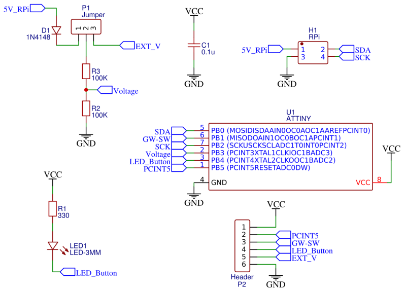
It takes the battery voltage and a connection to either the reset pin of the RPi or a connection to the charger that can turn its output off (ok, additionally you need GND and the I2C pins on the RPi). The rest is added by the Attiny on the small PCB.
I haven’t yet tested it with other power banks but when designing and programming it I had these other uses in mind.
Disclaimer: I’m the author.
I couldn’t find a schematic for the stock shield anywhere, but I’m keen to see one.
Ideas of maybe checking if any control IC uses external power components, and potentially has a similar enough footprint to be replaced by an ATTINY.
Any comments on the feasibility of such a hack?
Or are the ICs used more purpose specific / Integrated?
Schematic for the stock shield here:
https://brousant.nl/jm3/elektronica/104-geekworm-ups-for-raspberry-pi
Not there any more! Error 401
I’m the author of the project, and Simon allowed me to replicate his schematic under this link:
https://github.com/jbaumann/attiny_daemon/blob/master/miscellaneous/geekworm-ups1.png
I use Silicognition’s LifePO4wered/Pi+. Seems to be working great for the last 7 months or so since I got it.
I use it too, and this device is incredibly flexible and reliable, albeit a bit hard to configure at first.
Having the possibility to monitor battery voltage and current, as well as Pi voltage is definitely a plus that no other product i know offers.
I like it too, and especially the diligence and hard work that the author puts into it. My only caveat is the price. I set out to get to an overall price of around 20US$.
ATTinyDaemon monitors battery voltage and can monitor the RPi voltage as well, simply by setting a jumper.
Disclaimer: I’m the author of ATTinyDaemon.
About 5 or 6 years ago, I bought a new, very small Linux based computer that included power supply, 8″ touch screen, WiFi, USB ports, and a couple of flash memory card expansion sockets. It came packaged in a beautiful enclosure, and its detailed circuitry is freely available to download.
Despite numerous accidental power disconnects, its internal memory has never been corrupted. No UPS is required.
I also own several Raspberry Pi, and their GPIO is a welcome addition.
But the Chumby 8 is a hacker’s dream that continues to amaze me.
http://linuxgizmos.com/files/blueocty_chumby8.jpg
You could just use an old <$50 eBay Thinkpad, plugged in always, and as long as the battery has over a few minutes of charge you can just use the laptop as a UPS backed server and power a pi zero (pihole, etc) off 1A USB with a service to shutdown the pi when AC power goes out (stops charging)
My goal was to create a solution in the 20$ range. And starting with a cheap chinese UPS (that didn’t really work as intended), modifying it and adding the missing functionality seemed like a good way.
Since we have the designer in the comments…
Wondering why you went to the trouble of having a board made vs using the proto area the original product gave you in the unused space. All the signals needed can be tapped from the original circuit, which would have left the GPIO header free for another hat atop it.
This actually was my first idea. But examining the “proto area” showed that every hole is connected to GND. I do not really understand what the designers wanted to accomplish, maybe cooling the battery, or allowing air exchange between the RPi and the environment. Using this area would have been the perfect solution otherwise with minimal impact elsewhere.
But since I had an additional PCB anyway, I tried to minimize the dependency on the Geekworm. This way the design is usable for many other “half-baked” UPS solutions (and many power banks) as well, adding the missing functionality to have a full-fledged solution (see e.g. the Powerboost Charger board that could be used with the ATTinyDaemon as well).
And the board does not have to be plugged in directly above the Geekworm, you can have as many other HATs as you like and then plug in the ATTinyDaemon on top of the last one.
Disclaimer: I’m the author of ATTinyDaemon.