High-voltage experimenters are a unique breed. They’re particularly adept at scrounging for parts in all kinds of places, and identifying how to put all manner of components to use in the service of the almighty arc. [Jay Bowles] is one such inventor, and recently came across a useful device from Subaru.
The device in question is an ignition coil from the Subaru Outback. It consists of a pair of high-voltage transformers, connected together, in a wasted-spark setup to run four-cylinder engines. Having sourced the part from a friend, [Jay] realized that with some modification, it would make a great high-voltage power source.

The first job was to figure out how to remove the internal electronics that drive the transformers. In this case, it was a simple job of hacking off a chunk of the case, removing the interfering hardware. With this done, it’s possible to directly access the transformer connections.
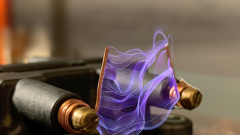
In [Jay]’s experiments, the device is run in an anti-parallel configuration, to produce higher than normal voltages at the output. In various tests, it’s demonstrated running from both a classic 555 circuit, as well as a ZVS driver. For future projects, [Jay] intends to use this setup to drive a large voltage multiplier, also noting it can be used with Tesla coils and plasma balls with the right additional hardware.
While [Jay] doesn’t include any specific model numbers, reports are that these coils are readily available in a variety of 1990s and 2000s Subaru vehicles. Others have used similar hardware to create high voltage projects, too – this stun gun is a great example.


Yep, ignition coils sure are a great way to learn about using coils to ignite things.
I think that some other cars besides Subarus might also use them.
Do Tesla’s use Tesla coils instead?
They do and Tesla’s next feature is the death ray security system that will be on the Model T
Teslas are powered by the big towers that fill the atmosphere with electriizical energy from the original Tesla plans. https://en.wikipedia.org/wiki/Wardenclyffe_Tower
The Ford Vulcan 2000 and up uses a wasted spark ignition coil box. They actually spec’d two different plugs for it, one with platinum on center conductor and one with platinum on ground side! They don’t make those plugs anymore so have to use double platinum and it’s so high voltage it still eats plugs!
Would it have killed the author to explain what “wasted spark” means?
Instead of a distributor to switch the spark to the appropriate cylinder, they use a center tapped secondary on the ignition coil with the center tap grounded. Each end of the high voltage coil goes to a sparkplug and 2 cylinders get a spark at the same time.
One each firing, one cylinder is charged with fuel-air and near the top of the compression stroke ready to fire and the other one is just ending the exhaust stroke and ready to begin the intake. The second one get s a spark but there’s nothing to ignite so the spark is “wasted”
It’s a trade off. You use more coils (1 per pair of cylinders) but no distributor (moving parts).
It also means one of the plugs gets a positive polarity spark and the other gets a negative polarity spark.
very good
Stuff like this makes me wish I knew more about working with high voltage. I’m glad I don’t though, because 1- I’d surly waste all kinds of time and money doing stuff with it if I did, and 2- my lack of knowledge keeps me from working with it, and thus, most likely electrocuting myself.
Honestly, that’s the best starting point for real experimenting. The moment you stop worrying about doing something stupid, or think you know everything/enough about it… you start bleeding/lose body parts. Perfect example? Hand tools. If I work with them for more than 10-20 minutes I WILL get into a zen state of thinking about the next 4 steps.. and cause myself to bleed EVERY time. Power tools.. I KNOW they will move past my thought processes, and I stay hyper focused.
That isn’t a Zen state.
probably true :)
But yes, please be SUPER careful with high voltage. It’s super fun though. Please be scared of it, and respect it.
In my childhood experience (playing with ignition coils from model T’s) it really hurt when you got shocked but there was nowhere nearly enough current to actually injure you, so in a way it was a good method for learning about voltage and ground paths. You knew it when you made a mistake.
Can I assume you stuck with it at 12V, and not mains power? Was it even 12V with the Model T?
6v in the Ford but 12v tolerant. People upgrade Model T’s to 12v to use modern batteries and lights, etc. and a real voltage regulator. They keep the starter and coils (4 of them. Coil per plug.) and magneto. The Ford Coil includes a vibrator to get AC. The 4 coils sound like a musical instrument with each buzzer having its own sound. Yes, I drove one in high school.
I once did this with a ignition transformer I got from a used car parts store. It worked really well!
Nice !! I wonder just how much current these coils may be capable of delivering ? Any idea ? Have you actually attempted to measure the HV output from these coils as well as just how much current they are capable of delivering ? I’d be VERY interested in knowing this data ! My interest lies in building vacuum tube, high power, ‘RF Power Amplifiers’, capable of between 1~2 Kilowatts between 50~54 MHz. Thanks very much ! Mark, Amateur Radio Station WN3SIX
I’d expect about 10-20 watts continuous would be about the limit for these. For kW power you should consider microwave oven transformers.
Thanks for the tip ! I didn’t really expect that the automotive coils would be good for the amount of current that I require which is no more than 1 amp, likely more around 500~600 ma is roughly what I require for a high power, vacuum tube RF power amplifier. Do you have any idea how much current a microwave transformer may be good for ? Since it is the HV power supply for a magnetron I suspect that it MAY produce enough current for my application. I’ll have to research the magnetron tube HV power supply requirement specifications. If one is able to be utilized it certainly would be wonderful as it would save about $500.00 or more as that is about the cost of a suitable ‘Peter Dahl’ HV transformer capable of around 3200 volts and capable of supplying the amount of current required for the vacuum tube that I have in mind, either a type 3-500Z triode or a type 8877 (Eimac 4CX1500). I appreciate your reply ! Mark..
Typical microwave transformers are 1500watt at ~2000V so about 750ma. Peak to peak voltage would about 2.8kV after rectification. You could of course use 2 in parallel for more current as long as they’re matched.
These are used a lot for Tesla coils so there should be data our there on the web. Do a search for MOT transformer for more info.
Thank you very much for the info ! That did occur to me to parallel a pair of them for more current. I’ll do my homework ! I very much appreciate you’re taking the time to share the info ! Take care, Mark..
No offense but you really don’t sound like you know what you’re doing. Above 1000 volts you have plenty to worry about like insulation resistance and corona discharge. Do you know what type of rectification and filtering you will need, diode PIV ratings, filter cap ratings, etc. You’re working with lethal voltages and one mistake can easily kill you. Do you really want to cheap out on parts that could kill you if they fail?
Lol ! No offense taken, no worries brother ! Although, from the questions I have posed and ‘off-the-wall’ notion of considering the use of one or more microwave, magnetron vacuum tube HV power transformers as a possible alternative, ‘McGyvered’ approach and MUCH cheaper alternative to purchasing a commercial “Peter Dahl” HV Plate Transformer, P/N: PWDP13026 to the tune of $400.00. Specifications are here: http://www.pwdahl.com/pdf/PWDP13026%20REV%204.pdf
In order to utilize a type 3-500Z vacuum tube an RF Power Amplifier, the Plate Voltage requirement is about 1,000 VAC +/- and capable of about .5 amps +/-, roughly stated. The ‘Dahl’ commercial HV plate transformer is a splendid choice for this application, however, quite pricey and not within my intended budget presently so I’ve simply been exploring other possibilities and the Hackaday article on the Subaru HV coils piqued my interest, although I had no expectations that an automotive HV coil would remotely come close to my requirements, however, it got my ‘wheels’ turning, considering other possible, and MUCH less expensive, alternatives and falling right into my mantra of re-purposing electronic components for various applications in order to save cash and, the bonus of rescuing perfectly useful components from their sad fate of winding up in a scrapyard otherwise.
I absolutely, 100%, agree with KNOWING and having the utmost respect for the very lethal voltages present within this type of electronic equipment ! I can assure you, I have the UTMOST respect for HV and ALWAYS follow each and EVERY safety precaution when working with it ! Ironically, I worked as an electronics technician for the U.S. Dept. Of Defense for 20 years troubleshooting and repairing HV (7000~12000 Volts) Switching Power Supplies utilized in Satellite Ground Communications Terminals as well as high power (up to 1000 Watts RF Output) ‘X’ Band, Microwave RF Power Amplifiers that are paired with aforementioned HV power supplies, surely, not a novice with this type of gear ! Lol ! Additionally, I have held an Amateur Radio Station ‘Extra’ Class License since 1976 after initially having started out in the hobby as an ‘entry level’ ‘Novice’ class licensee for about 8 months, at which time, doing a LOT of research and studying the required electronics theory and learning to both send and fully copy Morse Code at a minimum speed of 20 WPM (Words Per Minute), a mandated requirement at that time in history, upgraded to the highest, ‘Extra Class’ license, which permits full amateur radio operating privileges. It has been and continues to be a VERY interesting and enjoyable hobby !
I’ve LOVED and been very keenly interested in electronics and communications ever since the age of 7, when my father first taught me the Morse Code, who served as a former ‘Morse Code Intercept Operator’ having served in the U.S. Army Signal Corp. immediately following WW2, monitoring ‘Eastern Bloc’ ‘CW’ (Continuous Wave, commonly referred to as ‘CW’ by radio operators and transcribing what he copied on a manual typewriter which then went forward to the Cryptologists, whom deciphered it.
Well, I suppose that I sufficiently have bored you by this time so I’ll close this ‘short story’. It was a pleasure to have made your brief acquaintance !
Best regards, Mark, Amateur Radio Station, WN3SIX
That image is INCREDIBLE! Never thought to multiple expose hv sparks
Pretty sure most ignition coils would work… VAG, Ford, and Fiat/GM definitely have almost identical versions of these as the automotive industry tends to work along very similar lines.
Almost any 2-pin or 4-pin pack is going to be wasted spark, these days a lot of them have built-in driver circuits which either need a simple logic input to trigger them or possibly a FET driver chip, but the high-energy stuff is done in the coil pack.
Yup, think my spark record with a dual coil setup was a shade over 2 feet, probably well over 140KV.
Not sure to this day how, turns out that I’d inadvertently used two near identical units and adding additional insulation via the Epoxy brick method and quasi resonant setup with 2N3055 worked well then moved on to camera flash units though charged to a lower voltage than normal to preserve the coils at least temporarily.
Still have the working one, also oil filled seems tougher than solid.
Incidentally think this is how they were used in the car originally, the primary had a fairly large parallel capacitor
which evidently took out the worst of the reverse spike.
My idea was to connect this across both coils with the primaries in series, this did the trick.
An interesting mod wrt ridiculous voltages is to use an gas boiler ignition unit, some of these run on 9V and will run at considerably more than this though shorten their operating life in some cases to hours.
Think with these as with bug zappers the secondary is a resonant circuit so peak voltages are very high.
I did read somewhere that a “cool!” project is impulse powered fusion generators, based on a variant of the IEC.
In this case the grids and surrounding circuitry are designed for very high peak power, so rather than a continuous low power its all dumped into a single pulse once a second or so thus resulting in marginally higher efficiency.
Slight problem: this can also result in blown grids but to some extent you can mitigate this with careful design and voltage limiting and/or WB7 design features like running the grid coils from an isolated power supply.
On my “To do” list is fabricating some superconducting coils in their own little cryostat bottles, with the laser enhanced O2 method on BSCCO-2223 so the coils are monolithic.
10 turns per layer should work as its a HTSC and 4 layers with staggered windings.
All possible to simulate on FEMM.
I have the same setup with the coil pack and ZVS board but the only output I’m getting is a thin weak spark when I disconnect the power. I’m assuming the coil is good as I’m measuring 0.8 ohms on both the primary windings and 12.5 K ohms on the secondary windings. My ZVS is good as it powers flyback transformers with no problem. Any suggestions what could be the problem?