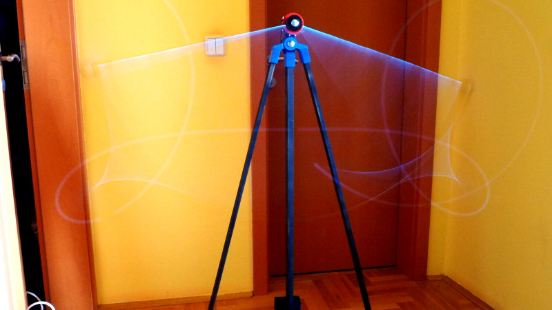
Rotating mechanisms can be a headache when it becomes necessary to deliver power through them. [Igor Brkic] faced just such a challenge when creating his double-pendulum build, and solved it with a little DIY.
The project is known as KLAATNO, inspired by the Croatian word for pendulum, klatno. It’s a mechanical installation piece, consisting of a power-assisted pendulum, with a second pendulum fitted at the end of the swinging arm. A 24 volt geared motor is used to drive the assembly. It’s controlled by an Arduino Pro Mini, which measures the back EMF from the motor terminals to determine the speed and direction of the motor’s movement.
To make the installation more visually striking, EL wire was installed on the swinging arms of the twin pendulums. This required the transfer of power to the rotating assembly, which was achieved through the use of custom made slip rings. Copper sheet is used in combination with a flexible metal wire sourced from a guitar string. It’s not as low-friction as [Igor] would like, but it gets the job done.
It’s a fun installation that would be perfectly at home in the common area of any university engineering building. Of course, our favorite pendulums are of the siege weapon variety. Video after the break.


klaatno berada nicto!
Very cool, but something has to be done about the noise…
wow, great scifi reference! :)
The interesting part is the pendulum drive.
Most of the variables are not actually `const`.
not sure what do you mean by variables not being const. I don’t know if the compiler actually stores global consts in flash and if it skips the stack for the temporary const variables in the code, but all variables I marked as const are the ones which aren’t suppose to change
I think he’s referring to the sensor readings you get from the motor EMF. Pretty clever.
Just a thought, could you use induction coils to send power to the EL? It would be far less efficient at sending power but I wonder if you would make up for that in reduced friction.
That’s a good idea. It doesn’t require too much power so efficiency isn’t a big deal. But it would require some additional electronics on both sides for transfer and conditioning (EL needs around 200V at 4-5kHz). I’ll most likely just change it to use two thinner ball bearings as two slip rings for the second arm. For the driving motor, all I had at the time was a geared one but direct drive would reduce the damping of the main arm quite a bit more.
Exactly.
Inductive power transfer for EL could be feasable as secondary output requires “high” AC voltage. I’d look into the Royer converter, though 5 kHz could require larger coils.
How about two fine wire coil spring separated by some space or one on each side of the axle/spindle wound against each other so the spring effect would be neutral at the centre position. Insulated from the spindle… they could easily carry that current and, no friction!
Nice, but i wouldn’t allow full rotations which can happen on both arms.
Clocks often use such springs for the windup
For a good description of double pendulum systems (calculation, coding, simulation in Processing) go watch the excellent Coding Challenge’s demonstration : https://m.youtube.com/watch?v=uWzPe_S-RVE