This Handheld C64 Design Study Needs To Be Made

The Commodore 64 remains the best selling home computer of all time, and is unlikely to be toppled anytime soon. It continues to inspire a diehard community of makers and hackers to this day. [Cem Tezcan] is one of those people, and his design study of a handheld C64 is utterly droolworthy.

It’s quite likely that you’d run out of power before the cassette finished loading, but hey, we can dream.

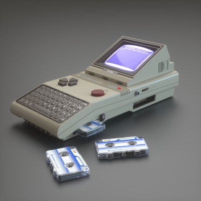
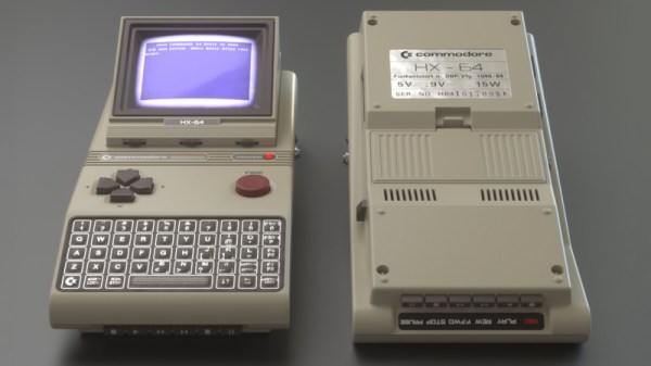
The study includes renders of the device from several angles, as well as a basic blueprint outlining the various components. It features period accurate hardware, using a membrane keyboard, micro-cassettes for data storage, and a 3.5″ CRT. Other nice touches are the big red textured FIRE button, and a horrible early 80s 3.5mm jack.

The C64 hardware of the time required both 12 V and 5V power, and the current draw of even a small CRT would be high. It’s likely such a handheld would have battery life measured in minutes. It’s a wonderful picture of what could have been, though we suspect that such a design would have pushed the limits of the technology of the time.

However, electronics has matured since, and we sit here rather comfortably in 2019. We’d love to see the best handheld C64 that the community can muster, and with 3D printers and FPGAs on hand, it’s an eminently achievable feat. Bonus points to anyone who can make a microdatasette interface, too. All submissions to the tips line, and meanwhile, consider how easy it is to build a new C64 from scratch. Happy hacking!

Double Pendulum Uses Custom Slip Rings

Rotating mechanisms can be a headache when it becomes necessary to deliver power through them. [Igor Brkic] faced just such a challenge when creating his double-pendulum build, and solved it with a little DIY.

The project is known as KLAATNO, inspired by the Croatian word for pendulum, klatno. It’s a mechanical installation piece, consisting of a power-assisted pendulum, with a second pendulum fitted at the end of the swinging arm. A 24 volt geared motor is used to drive the assembly. It’s controlled by an Arduino Pro Mini, which measures the back EMF from the motor terminals to determine the speed and direction of the motor’s movement.

To make the installation more visually striking, EL wire was installed on the swinging arms of the twin pendulums. This required the transfer of power to the rotating assembly, which was achieved through the use of custom made slip rings. Copper sheet is used in combination with a flexible metal wire sourced from a guitar string. It’s not as low-friction as [Igor] would like, but it gets the job done.

It’s a fun installation that would be perfectly at home in the common area of any university engineering building. Of course, our favorite pendulums are of the siege weapon variety. Video after the break.

Continue reading “Double Pendulum Uses Custom Slip Rings”

Music Box Paper-Punching Machine Settles The Score

As soon as [pashiran] laid eyes on his first hand-cranked music box, he knew he was in love. Then, he started punching the holes for his first ditty. As the repetitive stress of punching heated up his arm, his love cooled a bit. Annealed by the ups and downs of this experience, he decided to design a machine that can punch the holes automatically.

Soon, [pashiran] found his people — a community of music boxers that transform MIDI files to DXF format, which creates coordinates for CAD software. In [pashiran]’s music puncher, an Arduino MEGA takes a DXF file and bubble-sorts the jumble of x-coordinates. The MEGA conducts a trio of two stepper motors and DC motor. One stepper pushes the paper through on the x-axis, and the other moves the puncher head back and forth across the paper scroll as the y-axis. The DC motor moves the punch up and down.

Now, paired with [Martin] of [Wintergatan]’s method for chaining music box paper together, [pashiran] can write a prog-rock-length opus without fear of repetitive stress injury. And since he’s published the STL and INO files, now you can, too. Watch it punch and play 250 notes worth of “See My Vest” “Be Our Guest” after the break.

There’s more than one way to avoid manually punching all those holes. When [Wintergatan] was wrestling this problem, he inspired the hacker community to create a MIDI-to-laser-cut-stencil solution.

Continue reading “Music Box Paper-Punching Machine Settles The Score”

A Self-Expanding PWM Driver

For smaller microcontrollers, having enough outputs for the job is sometimes a challenge. A common solution is to do some sort of multiplexing with the available outputs or perhaps something more advanced such as Charlieplexing, but another good option is to use a specialized driver board. What’s even better is if you can daisy chain driver boards to get even more outputs.

[Eric] has been working on a 16 channel LED project but first wanted to build a driver board with 8 channels. Before building a full 16 channel version he realized that he could take the same 8 channel board, make a mirror image of it, and attach it underneath the first board with headers in order to double the number of channels available. Without having to build a separate 16-channel board, this shortcut saved [Eric] some time and a great deal of effort.

This is a great example of working smarter, not harder. Each of the 8 or 16 channels has full PWM support as well to support PWM dimming, and a similar board could be built for motor control as well. It’s a good illustration of how good design can end up working for you as well. And if you need even more outputs, Charlieplexing is one way to get them.

Continue reading “A Self-Expanding PWM Driver”

Finally Your Air Drumming Has An Outlet

Two engineering students are hard at work on this air drum which they hope will help disabled people and people in nursing homes. Though, we think it just looks fun!

Each board is its own module consisting of the electronics and 3D printed cases. The modules each contain an arduino mini, IR sensor, and LEDs. They share power, audio, and communicate with an i2c bus. Two modules are special, one holds the power system and the other a Raspberry Pi. The units can be put together in different configurations. Finally, they are capped with speaker units.

The demo shown in the video, which you can see after the break, looks fun. The response time is pretty fast and it looks like you can measure all sorts of parameters. This can then be translated into different velocities, pitches, and instruments. It’s somewhere between a theremin and a drum kit, very cool.

Continue reading “Finally Your Air Drumming Has An Outlet”

DSP Spreadsheet: IQ Diagrams

In previous installments of DSP Spreadsheet, we’ve looked at generating signals, mixing them, and filtering them. If you start trying to work with DSP, though, you’ll find a topic that always rears its head: IQ signals. It turns out, these aren’t as hard as they appear at first and, as usual, we’ll tackle them in a spreadsheet.

What does IQ stand for? The I stands for “in phase” and the Q stands for quadrature. By convention, the I signal is a cosine wave and the Q signal is a sine wave. Another way to say that is that the I and Q signals are 90 degrees out of phase. By manipulating the amplitude of I and Q, you can create complex modulation or, conversely, demodulate signals. We’ll see a spreadsheet that shows that completely next time.

Continue reading “DSP Spreadsheet: IQ Diagrams”

Needling Your Projects: 3D Printed PCB Probing Jig Uses Accupuncture Needles

Trying to probe a modern electronic circuit with tiny SMD components, without letting the magic smoke escape in the process, can be quite a challenge. Especially since we hackers have not yet developed the number of appendages required to hold 3 different probes in place while operating both an oscilloscope and a computer. [Giuseppe Finizia] solved this problem with a 3D printed PCB probing jig that uses acupuncture needles.

As part of [Giuseppe] day job as an engineer at an electronic forensics laboratory, he does technical investigations on seized devices, which involves quite a bit of probing. The jig consists of a base plate with slots in which PCB holders of various configurations slide to hold all shapes and sizes of PCBs. Around the circumference of the plate there are multiple positions for adjustable probing “cranes”, each of which hold an acupuncture needle that is crimped or soldered to a wire. Each needle holder has a bit of flex which allows it to maintain downward pressure for a positive connection.

Making one-off tools and jigs is arguably one of the best applications for 3D printing, of which this is a perfect example. You can of course point solder wires or use test hooks if you have something to grab onto, but for easily probing multiple point on any PCB, this looks like a damn good solution. If you’re trying to trace a single signal, a precision pantograph might be your friend, or you can add a foot switch to your oscilloscope for quickly checking a circuit by hand.

[Jonathon Oxer] from the YouTube channel SuperHouse did a very nice video on the jig and made some small modifications. Check out the video after the break.