This tip for creating glass substrate circuit boards at home might hew a bit closer to arts and crafts than the traditional Hackaday post, but the final results of the method demonstrated by [Heliox] in her recent video are simply too gorgeous to ignore. The video is in French, but between YouTube’s attempted automatic translation and the formidable mental powers of our beloved readers, we don’t think it will be too hard for you to follow along after the break.
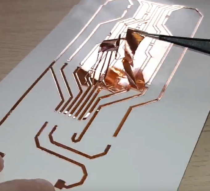 The short version is that [Heliox] loads her Silhouette Cameo, a computer-controlled cutting machine generally used for paper and vinyl, with a thin sheet of copper adhered to a backing sheet to give it some mechanical strength. With the cutting pressure of the Cameo dialed back, the circuit is cut out of the copper but not the sheet underneath, and the excess can be carefully peeled away.
Using transfer paper, [Heliox] then lifts the copper traces off the sheet and sticks them down to a cut piece of glass. Once it’s been smoothed out and pushed down, she pulls the transfer paper off and the copper is left behind.
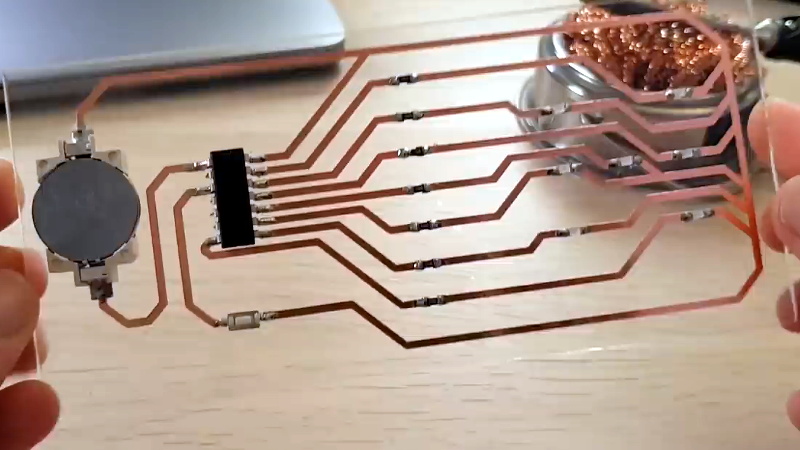
From there, it’s just a matter of soldering on the SMD components. To make it a little safer to handle she wet sands the edges of the glass to round them off, but it’s still glass, so we wouldn’t recommend this construction for anything heavy duty. While it might not be the ideal choice for your next build, it certainly does looks fantastic when mounted in a stand and blinking away like [Heliox] shows off at the end.
Ironically, when compared to some of the other methods of making professional looking PCBs at home that we’ve seen over the years, this one might actually be one of the easiest. Who knew?
[Thanks to James for the tip.]


Considering that HaD has had at least 3 other articles on glass PCBs, I’m surprised that none of them were linked to.
https://hackaday.com/?s=Glass+pcb
It’s when you use the glass itself as a delay line memory.
Wait, you could do that? How would it work?
Don’t know, so just speculating.
I’d think of sticking a piezo transducer on one end and another one on the other end. Pulse one of them, and read a time-delayed signal on the other one.
Don’t know how it would be used to store something, though. That would require some feedback loop, I’d guess. Maybe you could feed the signal from the listener-piezo back to the sender-piezo. The output would either be a pulse train or nothing. If you add an R/L network, you could change the pulse train into a steady voltage. And you could store 0 or 1.
Maybe you could even use the sender piezo to pick up the signal reflections in the glass, but I think that wold mean you would have to make 2 receiver circuits.
I guess you could do that with a slightly off angle laser and mirrored (or semi-mirrored) opposing surfaces. It would not be a long delay though!
I think the speed of sound is higher in glass than air, so wouldn’t be more of a delay line than airgapped piezos.
https://youtu.be/tQyX3F4ggM8
Well, not much ago, all TV set had a ghost image filter based in this principle.
Once upon a time I fiddled around with the adhesive copper foil that stained-glass artists use. I wouldn’t recommend it for very complex circuits, but it worked ok.
“Easy glass circuit boards”.
Because everyone has a Silhouette Cameo at home.
Or you can get a cutter head for your 3d printer. Or if you still have an ancient pen plotter. The Silhouette Cameo is “just” a pen plotter where the pen’s been replaced with a knife.
What do you think “easy” means?
I have one sitting in the back of the cupboard… :P
I should dust it off and put it to work. I originally purchased it to cut decals for front panels and masks for electro-etching.
One could also just use an xacto knife. It’s probably not for overly complex or mass-produced items. Just for very interesting and elegant looking one-offs. We shouldn’t overlook manual craftsmanship just because we’re accustomed to making cnc machines do everything for us.
It’s also pretty easy to add a drag knife attachment to any 2+ axis cnc, like a 3d printer. There are entries on HaD about that too.
https://hackaday.com/2016/06/05/cnc-drag-knife-upgrade-with-off-the-shelf-blades/
Hell, since the blades are just cheap disposable razors I’d just apply the copper to the glass and cut it straight on there.
everyone should, they are incredibly handy and I got a old but good cameo SD for like 28 bucks on ebay
I am guessing this is not feasible for any long term use due to the adhesive properties on the back of the copper, but maybe you could make some cool looking “visible” fuses – Definitely will look way cooler than a normal fusible trace when they go!
You could cover the whole thing with a thin layer of transparent paint or epoxy for increasing durability
what I was thinking, it’d keep the copper nice and shiny pretty too.
I was thinking the same thing, maybe it’s possible to find a clear coat that both works with glass and doesn’t dissolve the adhesive.
Applying it evenly is probably not going to be easy, but maybe it would work is one side had an extra inch of glass for it to drip off, and once it’s hardened you can just snap off the extra glass and excess clear coat.
This wouldn’t solve the bonding issue between the copper and the glass. That would be my primary concern. Copper thermal expansion coefficient is nearly twice that of glass so over repeated thermal cycles it would likely have separation issues from the glass even if you cover it with something. Standard FR4 thermal expansion rate is much closer to copper and the epoxy bonding between the FR4 and copper assist with the separation issue. I suppose if this glass circuitry were used in an application where temperature was held very constant it would last for some time, at least until the adhesive backing started to break down.
This is actually a damn good idea. This would be great for experimenters and teaching kids circuit layouts. Not advised for microwave transmitters of course, but still this is wonderful. Thanks for sharing this HaD!
… I’m not sure you’ve thought through the implications of teaming kids up with glass.
I wish you well though. In the grand tradition of science educators everywhere, I leave you with this traditional prayer of our people:
“May all your safety briefs be indeed brief. May your first aid kits be always stocked with primo disney characters bedazzled bandaids. And may all of your incident reports be one-pagers.”
Could use acrylic instead of glass if worried about safety.
Acrylic wouldn’t be ideal. As this requires surface soldering once the copper is laid. Glass can take the heat.
Actually a solid glass substrate might work well at microwave frequencies.
Might have some nasty stray capacitance though
I tried using pyrex (7740) in a microwave ion source for some experiments here.
At 100 watt levels at 2.4 gHz, it simply absorbed most of the energy and melted. I had to go to pure quartz to reduce the losses enough to make it usable.
Link: http://www.coultersmithing.com/AuxCP/uWaveIon.html
It’s not just a high dielectric constant, which in that case could be tuned out, it was plain old loss.
This is a fast, beautiful way to make boards. My suspicion, based on other adhesive-backed copper foils I’ve used, is that you want to be really fast on the soldering because the adhesive loses its strength when heated, so you’re relying on adjacent adhesive to keep the pads down. I do a lot of single-sided boards, and will try this out.
Yup, I had some of that copper tape for stained glass a while back and I tried laying out some circuits on some small slabs of paxolin with it and it was coming up. I think on stained glass you actually turn it into a small bit of solder H channel pretty quick, so doesn’t really matter it’s not sticky still, only that it’s retaining form around the glass.
Nice project, and video
Yeah yeah, nah. As I thought the first time HAD featured this idea “cool, but why?” Has anyone managed to electroplate or vapour deposit clear acrylic then etch that is per a normal PCB then embed the lot in more clear resin once constructed? Perhaps bare wire construction and clear potting is the answer, less heat issues with the plastic.
soldering on vapour deposited copper sucks I once tried it on a scrap piece :)
I’d imagine because it’s not thick enough to carry the heat, probably plating more on it would work better.
My first thought was: why not just put the copper layout at the bottom of a container, and cover with epoxy resin?
I actually used my vinyl cutter to make mask for etching pcbs. It worked pretty well for simple boards.
I’ll admit,
when I first glanced at the photos, I didn’t see the glass.
I thought it was some pretty cool wire structure circuits.
So the weight of all the component is supported only by the copper tape’s adhesive? The same glue you’ll probably burn when you’re soldering components on top ?
Does not seems that good to me…
Plenty of aesthetic hacks makes it onto hackaday on the merit of being ,… well, a hack. Personally I think this is a gorgeous one.
So the next level would be to etch the glass with patterns, and send the light into the glass like how some people do with acrylic. Not only is the circuit on the glass, but the glass is part of the display as well. Then combine the art of the PCB layout with the art of the glass, but it would take someone pretty creative to figure out a good design.
What about glueing the copper film on the glass and just do as a regular PCB
This could be an easy way to make, replace or duplicate broken PCB’s in a post-civilization world.