Assembly lines for electronics products are complicated beasts, often composed of many custom tools and fixtures. Typically a microcontroller must be programmed with firmware, and the circuit board tested before assembly into the enclosure, followed by functional testing afterwards before putting it in a box. These test platforms can be very expensive, easily into the tens of thousands of dollars. Instead, this project uses a set of 12 Raspberry Pi Zero Ws in parallel to program, test, and configure up to 12 units at once before moving on to the next stage in assembly.
Fixing Fixture Bottlenecks
The company where I work, Propeller Health, develops IoT products that are assembled in a way similar to many other companies; there is a circuit board and a plastic enclosure. The bare PCBs go through SMT twice (components on the front and back), then they go through ICT (In-Circuit Test) where they are programmed and pogo pins on each of the test points verify all components on the circuit. They are also given a unique MAC address for Bluetooth based on a 2D barcode sticker placed on the board after SMT. After that they are assembled into the plastics and run through a functional test fixture before they are put into inventory mode and boxed. We have a product line of around a dozen different devices, and each uses a different PCB and enclosure.
Production runs need test and programming fixtures, a topic i wrote about a few years ago. To increase scale and reduce costs we started working more closely with our contract manufacturer to identify and fix the bottlenecks in the assembly line process, and we noticed that the ICT stage was taking 6 minutes for a panel of 6 boards. The ICT section itself was relatively fast, but the firmware programming and mac programming were taking a long time because the test platform was not capable of multiple simultaneous serial port connections.
This was a $30k fixture with 6 Segger programmers, 6 Keysight scanners, sitting on top of a $100k Teradyne platform, and it was our biggest bottleneck and greatest expense. Further, each device in our product line requires different fixturing. The combination of these expensive fixtures and slow cycle time was making our COGS (Cost Of Goods Sold) untenable.
On an assembly line, time is literally money, as every cycle time for every operator on the line is measured and added to the cost of the product. Reducing a cycle by even a second adds up quickly over a volume of thousands. Over 10k units, 2 second reduction is 6 hours of labor, at $15/operator hour is $.01/unit, and CMs, especially US based ones, are charging more than $15/hour. Having a 6 minute cycle time for 6 pieces was ripe for improvement.
Stage One – Arduino
The first stage was more a proof of concept. Could we pull some of the functionality off of the expensive ICT fixture onto a cheaper faster fixture so that we could scale in serial instead of buying another fixture to scale in parallel?
For this stage we implemented a feature in our firmware we call self-test, which is similar to a JTAG boundary scan. Rather than placing pogo pins on every net, we put a feature into the firmware to run a self-test on as many components as it could, and report the results over serial. This way we’d be able to connect only with the power and UART pins and get a complete and very fast readout of what exactly failed. Eight Arduinos connected via a USB hub to a tablet PC with a custom Python script and interface was the solution.
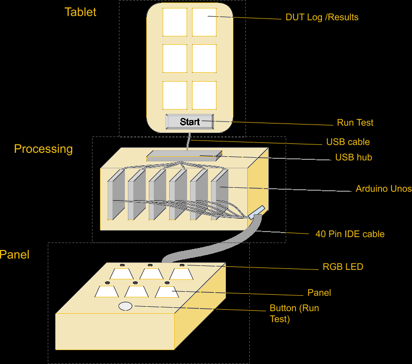
A single 40pin IDE connector was enough to have power, an RGB LED, RX, TX, and a single button that would kick off the cycle for all 8 at once. The Arduino would request a self-test from the DUT (Device Under Test), which would test its components and report back. Tests included verifying that sensors were reading values within an expected range, but also turning on the LED and buzzer and measuring the voltage drop to verify that outputs worked as well.
This worked, and proved the concept of creating a box with most of the electronics paired with a simple customized fixture for the panel, but it wasn’t enough. Pulling out some of the circuit tests was insufficient to reduce time significantly. We needed to pull out more tasks.
Stage Two – Raspberry Pi
One of the more expensive parts of the ICT fixture was the Segger J-Link programmers. If we could pull out programming from ICT with something cheaper, we could reduce fixture costs significantly. Many chip manufacturers offer programming at the factory so that your microcontrollers come on a reel with your firmware pre-programmed. This is useful when you don’t trust your manufacturer or don’t want to have a special fixture for programming, but it does have an added cost, and there’s a lead time, and changing your firmware is more difficult, and you can’t use that part on any other product.
Programming in house had a lot of appeal for us, simplified our supply chain, and gave us more flexibility to change our firmware and shift inventory as needed. Enter the Raspberry Pi Zero W and OpenOCD. The Raspberry Pi is more than capable of running OpenOCD to program a microcontroller, and was surprisingly easy to configure and get running. It also had a serial port and GPIO for controlling WS2812B LEDs, and was small enough that it was easy to put a bunch in a box.
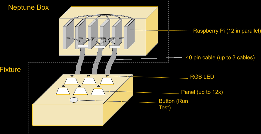
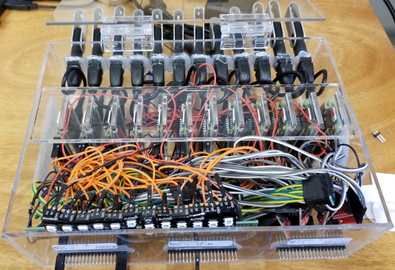
The connector expanded to a second 40pin IDE cable, and support for up to 12 parallel units, the size of our largest panels. Each Pi runs completely independently, without communicating with each other. The only thing they have in common (besides power supply) is that all 12 are connected to the same pushbutton on the front of the fixture. The button is used by the operator to start the programming cycle, but each Pi runs its process independently.
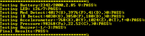
Drawing on the Arduino experience further, the Raspberry Pi process would first program the unit, then verify it was programmed correctly by communicating over the UART, then execute the self-test on the device, which would test the accelerometer, microphone, IR sensors, LED, buzzer, etc, and report back the results and a PASS/FAIL status. We had accomplished our primary goal of removing a significant portion of the process time and cost from the ICT fixture, but we could go further.
Stage Three – Adding Features
With the addition of cameras to the fixture, we could read the MAC address on the sticker and use the serial port to program the MAC address into the unit. This allowed us to tie our process to the MAC address that was used to track the unit through the rest of the assembly line.
If you’re wondering why we didn’t pre-assign numbers and then have the operators put on the correct number, it comes down to reducing the chances for operator error. Giving the operator a sheet of stickers and telling them to put them on the units is way less error-prone than having them put specific stickers on specific units, and faster than printing out barcodes one at a time for individual units.
Next we added the unique key stored on the unit for authenticated communication. The pi generates a 64 byte key, programs and verifies that key on the sensor, then encrypts the key and stores it in the log file. That key gets decrypted on our servers and allows us to communicate with our sensors.
In addition, we added thorough logging; a system log tracks the version numbers of the script, config file, and firmware file, and a separate file logs each cycle with diagnostic data about each stage of the process. These logs are stored on a thumb drive, but also uploaded regularly to a secure FTP so that we can import the logs (and the encrypted keys) immediately, as well as keep tabs on our CM and monitor when they are running our jobs and help them diagnose any problems.
We also made all of this run off a thumb drive. On boot the pi starts a Python script whose sole job is to wait for a thumb drive to be inserted, then run the script on that thumb drive. The thumb drive contains the main Python script, config file, firmware hex file, and logs. This way we have a single box that is completely agnostic to the assembly line, and then we have a dozen thumb drives that stay with the line for that particular device. We don’t need an interface to the pi because we can just plug the thumb drive into a computer to configure it however needed. Anything that makes the job easier for operators makes the assembly line run smoother, and saying “plug these into the back of the box” worked pretty well.
At this point we could program the microcontroller, then execute a self-test, then program the MAC address, and generate a unique key, and output to an LED the status of the process (green for success, yellow for in progress, and red for failure), and save the log to a file. This shaved MINUTES off the cycle time. Before, a panel of 12 was split in two, then each half went through the ICT fixture for 6 minutes, for a total cycle time of around 12 minutes for 12 devices. After the change, we had the full panel of 12 take under a minute, then split and spend under 2 minutes each at ICT. We went from 12 in 12 minutes to 12 in 5 minutes, with more control over the process and greater transparency.
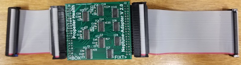
Stage Four – Neptune is Alive
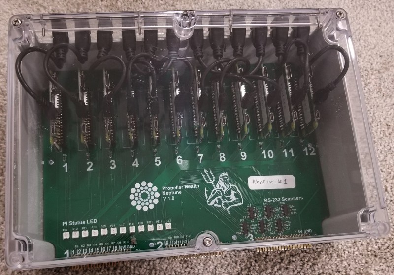
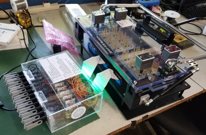
After our first box worked, our CM asked for more so they could service multiple assembly lines, plus have backups and one for test/development. The design was formalized, we found a new enclosure that could be modified easily, and designed a PCB. Total cost for all components is around $500, and the PCBs are easy enough to assemble by hand in a couple hours. We called the project Neptune and the boxes started coming together. Now we have plenty of Neptune boxes, and we have a spec for our fixture developer that allows them to have a very simple circuit they can replicate over and over. Fixtures are rugged beasts that require special knowledge and experience that we don’t have and don’t want to develop, so we outsource that part. The most recent fixture worked immediately with no changes, which is usually nearly impossible.
Stage Five – Changing Cameras
A MAC address sticker is placed on every unit after SMT, but this address must be programmed into the microcontroller itself. To do this, a barcode scanner is used. This is a production environment, and we are packing 12 scanners into a small space, and the scanners must accurately and reliably detect a 2D barcode about 1/2in^2, so not just any scanner will do.
Originally, on the suggestion of our CM, the fixtures were outfitted with Keyence scanners. After we discovered that these are $1400 each, we realized a huge potential for cost reduction. Each of our fixtures has 10-12 devices per panel, so replacing the Keyence scanners with $250 Zebra scanners was an immediate gain. The downside is that our Neptune PCB was designed for RS232 communication with the Keyence scanners using only 2 UART pins, and the Zebra scanners required 5V logic levels with hardware RTS/CTS pins as well. Fortunately we were able to build a cable with an inline circuit that contained an ATtiny84 for each of the cameras.
With a small config file change, we can tell the system to use a slightly different communication protocol. The Pi sends a serial signal, which is stepped up to RS232 inside the Neptune box, then on the cable dongle it steps down to 5V, goes into the ATtiny, where it is parsed, and if the desired signal then it sends a pulse to the trigger pin of the Zebra scanner, which then scans the barcode and sends the result back to the dongle, where it is stepped up to RS232 and heads back to the unit. The dongle meant that we didn’t have to change anything about the box, and the fixture didn’t have any additional circuitry as well.
Results
The results of Neptune have saved the company a lot of money in fixtures and in unit cost, improved our scalability, given us greater transparency in our production, added features, and made development of new features easier. The Raspberry Pi was instrumental in this, as was OpenOCD. We learned a lot and developed some techniques that would likely be valuable to anyone else doing manufacturing of electronic devices. We’re still working out exactly how we can share this without compromising security or trade secrets, but this is our first step.


This is great! I really enjoyed reading it. There’s only one thing missing from this and it left me thinking I was missing something, but I re-read the article and couldn’t figure it out:
What’s a CM?
(The first person to say “A centimeter, dummy!” will be moved to /dev/null)
Contract Manufacturer
Coulomb times molar concentration, dummy. But seriously, probably “contract manufacturer”
A centimeter! I think Heartbreaker suggestion of contract manufacturers makes sense. We do have $15 wages in USA. Most likely contract manufacturers.
I was just going to comment on my confusion of Contract Manufacturer and Contractor.
So, here is my amended version.
While a CM may pay its employees $15/hour, a supplier of contract labor (such as Manpower)
will charge the customer 3 times that (or more) per contractor.
Well it certainly isn’t a centimeter because there is no such thing. One country doesn’t have the right to rewrite another country’s language just because the newer country is especially illiterate.
“A centimetre (international spelling as used by the International Bureau of Weights and Measures; symbol cm)”
I’m sure glad the IBWM isn’t using Cyrillic or Mandarin characters!
problem with these things in the long term if your serious about making something is you end up spending a ton of development time and when the one guy on the planet that understands it, fucks right off, you end up spending a ton replacing it with off the shelf equipment.
if you are just doing it for a small batch run of widgets sure its fine, but when you start talking serious to a CM and start having tooling made instead of slapped together its time to put on your big boy pants
That is why proper documentation and backups exist. No doc, no pay mister.
Exactly this!
Although with this being relatively common hardware and all the tricky bits are off the shelf – no complex custom pcb festooned with unlabeled chips of indeterminate function makes even this limited post is enough to make it pretty trivial to support. Even if the Documentation is lacking. Not that that is a valid excuse for it to be poor, but accidents happen documentation goes missing after years in service etc.
until the OS gets tweaked, or specific version of PI is no longer available or some OSS python script gets forked cause the original author cant be bothered
we are not talking decades here folks, rather a year, go totally noob for a min and goolgle pi power off switch and see how many hundred of broken scripts and tutorial’s there are
spend a buck, maybe not 1000 but talk to your reps, your not the first factory to program 12 devices at a single go … hell we are doing 8 and its a 500$ box that plugs into USB and I did not have to invent, maintain or manage it, its a box
Embedded like this in the real world the pi’s are unlikely to see any software updates at all. Even more so as they are not connected to the outside world so don’t actually need the remote exploit fixes. So it really doesn’t matter at all if the entire software stack onboard would need re configuring to work with an update.. It just isn’t going to happen. (And odds of properly documented devices being so borked by somebody else updating (or not updating to keep up) that it isn’t trivial to fix are almost zero too.. step changes in linux that change how things work so completely are very very rare, and so far 100% optional if you join in or not)
As for Pi availability that is measured in years upon years. Just look at how long the earliest models of Pi have been available. And should things like barcode cameras need replacing because its not a magic locked down box but a Pi powered device it can easily be done. And even if that model of Pi is finally EoL when you need replacements odds of future pi’s being pin compatible are really really high, and any software you are running will at worst need a recompile.
I wish this rule existed at my last software dev job …
Valid point. We’ve actually been burned before when our fixture manufacturer went out of business without warning, so even when going the big boy route, stuff happens. We make medical devices that are regulated, so our QA team is fantastic about making sure we have all our ducks in a row as far as documentation. We have code reviews, electronics design reviews, thorough documentation on all parts of the project, including all parts of the assembly process; if I leave the team they will easily be able to go on without me.
RPi cameras were not an option?
Zebra cameras are built for barcode scanning. Probably saves a lot of development time over using a pi camera. They are normally usb or serial and you can say scan and it will return a barcode value. Could of been a single pi camera at a higher level and scan all at once? but that would require a lot of code to implement and probably not very repeatable. these things have to be poerfect and focused just right. Also they come with LEDS to help contrast the image just right for scanning.
FYI: the BON (bed of nails) fixture is probably ~$10k. probably 20-30k for that thing with all the stuff and coding. Still less then a 100K teradyne machine that is spending way to much time programming when it should just be doing circuit testing.
In my job we typicaly come up with some kind of gang programming fixture to reduce time. Our images are 60-100MB and that takes time to load onto NAND memory.
As far as the other poster about the one guy that leaves…well this is how these things work sometimes. Cost is always critical to production process and one guy building this is cheaper then putting on big boy pants and shelling out 100-200k when you ROI is not high in the first place.
As for most of my larger projects we spend around 500k in production assembly/test not including tooling for metal/plastic parts. FYI: We build security cameras.
This was a great post. love to see more like this. I would send you some of my stuff but no NDA with HAD :) Maybe when we have a product that is EOL. I have a couple 4 up programming fixtures that never got used, maybe i can find pics and give info on them.
ya know there options tween cobbling together something for a penny on a proven unstable platform like a pi right, and spending 100k on a teradyne
“proven unstable” hahahahahahah okay
Possibly with ZBar? I found this tutorial which uses the Python bindings on a Raspberry Pi 3: https://www.pyimagesearch.com/2018/05/21/an-opencv-barcode-and-qr-code-scanner-with-zbar/
FWIW, I use (and convince my friends) “pies” for the plural of raspberry pi. It’s phonetic and looks less like a minor misspelling of the product of urination. Just sayin.
Yeah, it is confusing, but “pies” is a food, not an SBC.
So, let’s think of something else…
Raspberries Pi?
How about make “Pi” the plural form as well, just like for “aircraft”? Or “Piez”?
BTW, try pairing a Raspberry Pi to an Echo and Alexa would call it “Raspberry Pee”. A subtle hint that Amazon doesn’t like a cloud-free alternative?
Great Write up!
“Propeller Health”,
I imagine that walking into a moving propeller is not very healthy.
Never hear the propeller complaining.
Looks like you never tried hobby drones. Usually propellers explode (and cut your hands) when you upset them.
12 keyence scanners would have bought a pretty decent inline laser engraver that could have been used on other products
I implemented a ‘unit self test’ command in exactly the same way for a product. An excellent way to exclude a whole bunch of potential faults. In mine, the PCB was connected to a test harness which had a bunch of loopback connections and some simulated components that would be found in the real environment.
Even initiating the self test tells you the processor is programmed and running, the power supply is ok, and the UART is connected and working.
After looking at the self-test report our CM could immediately see which boards could be re-worked, and which boards were either dead, or needed to go back to us for analysis.
Engraving the MAC address to the PCB with laser would not be an option?
Obtaining 12pi zeros? That is the biggest challenge
I bought 70 in one batch from AliExpress with no issue.
Why you used 12 cameras? For sure there are cameras which can scan all 12 barcodes at once.
haha, have built several production testing equipments like this during the last 2 years. the great part is that with a slight modification it turns into a good integration testing node that can really speed up sw development.
Yes and also helps when products require post mortem diagnostic after mystery failures. I build one for production QA and SW on target testing.
The use of a pi for programming reminds me of a product SparkFun sells for programming AVR: https://learn.sparkfun.com/tutorials/raspberry-pi-stand-alone-programmer