We wish that all the beautiful animations that are available today to understand math and electronics had been around when we were in school. Nonetheless, they are there for today’s students and [Learn Engineering] has another gorgeous one covering LC oscillation. Check it out, below.
If you are thoroughly grounded — no pun intended — in LC circuits, you probably won’t learn anything new. However, the animations are worth watching, just to admire them, if nothing else.
We were amused by his statement: “… looks as if the capacitor is saying: ‘you take the energy’ and the inductor then says, ‘no, you take my energy.'” Then we were further amused by [Seraph’s] comment which added, “Resistance in the circuit: ‘Alright, I’ll take the energy, then.'”
Of course, there are other ways to think of an LC circuit. The math isn’t that hard. Most of us learned that the circuit’s mechanical analog is a mass on a spring or a pendulum. The mass’s potential energy stretches out the spring until the spring then pulls it back until the potential energy of the mass pulls it back down.
If you want to experiment virtually, try the Falstad simulator. Just remember that if you think the sine wave isn’t dampening to look at the scale. As the sine wave dampens, the simulator will adjust the scale so you keep seeing approximately the same size sine wave.
We never get tired of watching the Fourier series explained graphically. Or anything from [3Blue1Brown].


Would it have killed the writer to include one sentence starting with “An LC oscillator is…”?
ATTENTION: the follwing replay contains sarcasm
Dear “old guy”, I don’t think it would have killed the writer to do so, but everyone knows that LC stands for Liquid Crystals. So this item is about displays. Or perhaps it stands for Laptop Computer, Learning Center, Life Cycle, Left Click, Level Control, etc. Who knows?
Ohhh… wait, now I see it… there is a inductor (L) and something that looks a bit like a capacitor (C), yeah… that must be it. This is all about THE MOST BASIC ELECTRIC OSCILLATING circuit you can imagine. How could I have missed this.
So perhaps it is best to reply to your comment with another question: “Would it have hurt the reader (old guy) to click onto the video that this Hackaday article is all about, as that clearly explains that this is all about an LC circuit.
Just as there is no perpetual motion, what is going on with an LC circuit is really resonance not oscillation. I’ve always had a hard time with semantics, particularly at the entry level of electronics because it requires the students to have to unlearn things to progress into active oscillator design. Nice graphics but the explanation lacks some necessary fundementals which may be a little unhelpful for the progressing student.
His terminology is correct. The circuit is oscillating because the current is changing direction periodically, even if only for a short while. This is known as “damped oscillation”, as he said, and the term does not imply that it does so forever. That’s what the “damped” part means. Don’t confuse “oscillation” with “oscillator”. An oscillator is a circuit that can sustain continuous oscillation.
The damped wave is never created without an external input that starts the oscillation at the resonant frequency. The oscillator is an active circuit which produces periodic voltage or current signals. The resonator is a passive device whose impedance changes rapidly with frequency over a very narrow frequency range. A crystal is very resonant but you wouldn’t refer to a crystal as an oscillator or expect to see waveforms if you connected across it unless you had external power which would set up the resonance. The external power applied to a resonant circuit creates the oscillations, not the LC circuit. Hence my comment about having to unlearn things to fully understand the next steps of oscillator design.
It’s a resonant oscillation going on in the LC circuit. Like when you strike a tuning fork. Let it go.
Tuning fork???
“The external power applied to a resonant circuit creates the oscillations, not the LC circuit.”
A tuning fork doesn’t just sit there, oscillating all day and all night.
That’s the hard part of unlearning things. An LC circuit is not an oscillator.
This is why I said, don’t confuse “oscillator” (the circuit) with “oscillation” (the process of swinging between two states). You seem to limit “oscillation” to mean continuous, indefinite oscillation. But you are the one who is wrong. What you are calling “resonating” is in fact oscillation. I agree that the oscillation does not occur without an external input, but that doesn’t keep it from being an oscillation. Sometimes you have to accept that a word does not mean what you would like it to.
The article is titled ‘LC Oscillators, Animated”. A bell can’t ring itself. An LC circuit is strictly passive until energized by an external stimulus. Important fundamental to know if you are progressing to oscillator design.
Not about right or wrong, more about a preferred concept to avoid misunderstanding. Resonance is such an easily understood concept as we are surrounded by bells, tuning forks, whistles, pendulums, pipe organs, etc., and the parallel LC tank circuit is an analog to all of these. I agree that the results of the reflection of the charges and currents between the capacitor and inductor are indeed oscillations and represent the circulation of the power of of the input stimulus. Damped waves decay because the stimulus power is eventually turned into heat with resistance. I would have liked to see more of these fundamentals in the video, IMHO. Just saying.
By the way, the most common application of a parallel LC circuit is as a bandpass filter where any extraneous (damped wave) ringing is considered a design flaw.
I am going to be a new electronics student and im wondering if you could elaborate on what you mean by “reasonance not ossilation”. Looking around the internet most people to define reasonance as an ossilation under special conditions and then have slightly different semantics as to what those special conditions are.
https://www.quora.com/What-is-the-difference-between-oscillation-and-resonance
https://wikidiff.com/oscillation/resonance
These links suggest that “resonance is the condition of being resonant” which seems a less helpful and more circular definition.
The system seems to be moving between two states and so intuitively I’d say its also ossilating.
What is the difference between the semantics why is it wrong to say its ossilating?
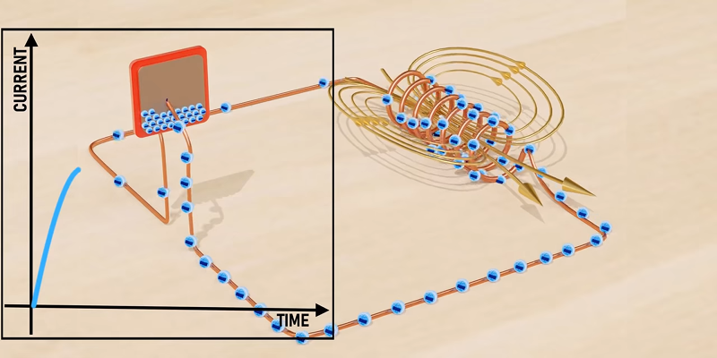
I’m a little surprised he didn’t show a separate graph showing the charge across the capacitor. I think this would be helpful for a lot of people, to see how the energy – not just the current – gets passed back and forth between the two elements.
Another great channel is called “Physics Videos by Eugene Khutoryansky”. Sometimes the animations are weird, but they get the point across in an interesting way.
The video is completely wrong. It shows both the charge in the capacitor and the current in the inductor to be zero at the same moment, which isn’t the case. If that were true, no magic would create the back-emf.
The entire point of the resonant circuit is that the LC circuit causes a phase shift between the voltage and the current waveforms, where the voltage is zero when the current is at a maximum, and vice versa.
Glad I’m not the only one who noticed this. Unfortunately this animation may cause more confusion than it clears up.
UGH!!! Oh my gosh what a terrible animation! It indicates that the current on one leg of a 2-leg component is different than on the other leg of the component. This TOTALLY wrong. Wow… I’m glad I didn’t learn electronics this way, because I’d be confused as heck! If you are learning electronics, please do yourself a favor and don’t use this video as a guide. The electrons do not actually move like the blue dots do in this video. The Falstad simulator is far better.
Technically it is not completely as current propagation is not instant but almost instant ( near lightspeed). But I agree, this animation is very deceiving.
The worst is that the blue things (electrons?) flow all the way around the circuit, and the current doesn’t “stop” until the last one has made it’s way over to the other side. This reinforces the “electrons travel through wires” misconception, which already confuses a fair fraction of folks.
(When the battery wants an electron, it just pulls it out of a copper atom in the wire right next door. This hole gets filled by another atom in the copper wire, etc. In the end, of course, one pole of the battery gains an electron and the other loses one, but it’s like people scooting down to make room on a bench. No electron needs to move more than one seat over.)
This intuition is not trivial. It gives rise instantly to current conservation, for instance. Getting it right helps students.
According to ELI the ICE man, none of this silly resonance thing would work if there wasn’t a time difference between current flow and voltage charges and an opposite but equal reactance “at some specific frequency” between capacitive and inductive reactance and the storage of power in electrons (Coulombs) in the capacitor and the creation of counter EMF in the collapsing field of the inductor. Of all the stories in electronics the simple LC circuit might be the most complex and interesting. Really important to get the concepts right from the get-go. And that is just the parallel tank. Series LC is just as interesting.
As far as one electron being attracted to move by the hole instead of an additional charge that pushes, that is likewise interesting. No matter how much we say we are applying power to a circuit by applying a positive voltage we know from vacuum tubes that all power flows from the negative terminal. The truly hilarious thing is that we do all of our designs based on a positive voltage model and it all works anyway.
It’s unfortunate they didn’t explain WHY the circuit behaves as it does, rather than simply stating “this happens, this will happen, this HAS to happen, this can’t happen…”. I have a basic understanding of how it works, but viewing the video from the perspective of someone who doesn’t, this video only succeeds in making the subject more confusing.
Terrible video.
They don’t describe that RC circuits don’t oscillate because the energy is dissipated as heat. Watching their animation would leave someone who is inexperienced to believe that the capacitor is negatively charging when current is flowing (it’s the same current animation as with the LC circuit).
Pedantically, the animation of current shows it trickling at the end (one electron at the end of the current going around the circuit) when in reality the electrons are all pushing on each other like is shown in the Falstad simulation.
The Falstad simulator does a hell of a better job in showing how this works than this video.
Exactly. Doing electronics for 30 years had me scratching my head at the electrons moving from one plate to the other in the RC circuit, but never coming back. Really shitty vid.
Sorry kiddos, there’s a shit-ton of shitty explanations out there; this era’s EE-student weedout process isn’t going to have anything to do with a student’s ability to understand the material, and nearly everything to do with whether years of targetted search data gathered from disney through xbox games results in targetted-results like this. And/or your ability to recognize shitty explanations. Basically, you’re gonna be spending *more time* sifting through crap than understanding material the old way. Shame