It’s hard to part with some things, even if they’re broken and were worth next to nothing to begin with. But some things are just special, y’know? And we would say in this case, the thing was definitely worth saving.
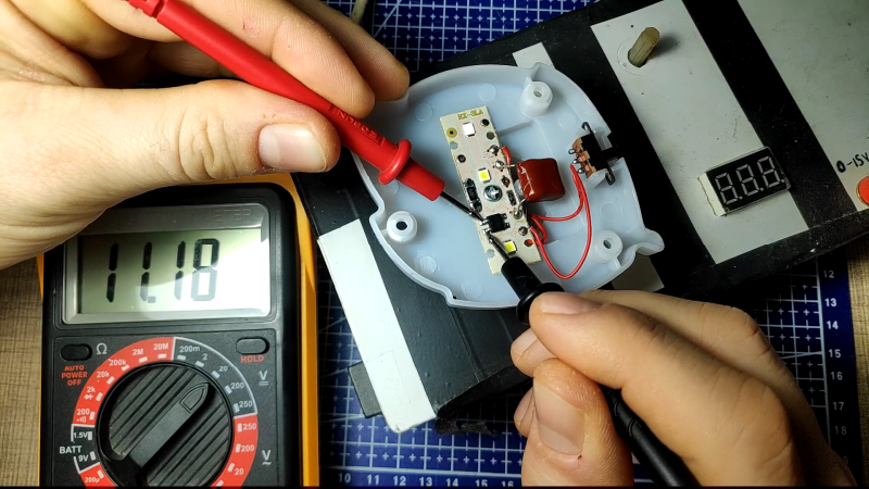
[Taste the Code]’s daughter’s beloved night light had a terrible flickering problem, and then stopped working altogether. Eager to make her happy, he cracked it open and found that one of the wires had disconnected from the outlet pin it was soldered to. That’s a simple enough fix, but trying to solder in tight quarters where the walls are soft plastic can be quite challenging.
Once that was fixed, [Taste the Code] plugged it in to a test outlet. It’s back to working, but also back to flickering, because there is no capacitor to smooth out the signal going to the LEDs. [Taste the Code] measured the voltage drop across the output of the bridge rectifier and soldered in an electrolytic cap with more than double the necessary voltage rating, just to be safe. You can check out the video after the break.
This goes to show several things: one, you can learn from fixing and improving cheap electronics from the likes of your local dollar store. Two, you can also get some kinds of components there quite inexpensively from things like magnetic sensor-based window alarms and dirt cheap solar garden lights.
You can also do some fun stuff with those cheap IKEA lamps designed for children. Here’s an adorable cloud lamp with an RGB LED upgrade that shows the weather mood using an ESP8266.


This definitely gets extra bonus dad points.
A simple little thing but it no doubt put a smile on his daughter’s face. Tinkerers make the best dad’s in my book.
And the best moms! Why not just the best parents?
This is just a nice story not about a nice parent, not a dick (or no dick) measuring contest, lets cool the P.C.
As Big Clive has pointed out, if the LEDs should fail or become disconnected from the bridge rectifier (there is already one dry joint!) then the FULL MAINS VOLTAGE will appear across the electrolytic capacitor which will surely explode!
The correct voltage rating for that electrolytic capacitor would be greater than the peak mains voltage. As the plug is a common European type the appropriate value would be at least 305 V.
Ignore this warning at your peril!
Normally a zener used to be in parallel with the capacitor. But I assume small cap = small blow. Ok, moderate blow :) But you’re right, you must know what you are doing when playing with the mains.
When I designed such a circuit for use in an approved* smoke alarm it had a zener as mentioned that was necessary for the correct function of a battery charging circuit. However, in this nightlight I feel that passive protection by using the correct voltage capacitor would be more appropriate. And simpler.
[*] Don’t ask! We spent more time getting it approved to the European Standards than designing it. (Not complaining).
Or add a ~18V Zener or Transil diode across the capacitor to limit the voltage it may be exposed to.
Should be a fix of less physical volume than using a 400V cap.
Makes your daughter sleep well at nights without the risk of spontaneous disintegration of the gadget.
Is the zener diode able to handle the current, if it will be the only think in the circuit?
Sure. The current limiting factor is the series capacitor at mains input. It will limit the current through the rectifier and the whole remaining circuit to some 20 mA.
I leave the math for you to complete ;-)
Actually, the maximum energy going into an unprotected capacitor won’t be more than roughly 250 mW so one could argue the likeliness of a big capacitor bang is reasonably low. The heat dissipation will be shared among both capacitors in the circuit in such case. I would expect the electrolyte to dry out over time leaving an open circiuit finally. Of course that behaviour is not guaranteed by its specification.
However, you would certainly need to replace the capacitor(s) once that happens.
I don’t think it is mentioned anywhere here, but the electrolytic capacitor is polarity sensitive. Be sure to get it in the right way around.