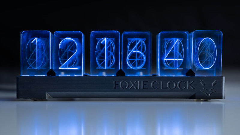
Nixie tubes are a hacker favorite for their warm glow and elegant, mid-century numerals. They’re also a pain to drive, demand high voltages, and aren’t exactly cheap and easy to come by. Never mind, for there are other ways to go – as [Alex Fox] demonstrates with the Foxie Clock.
The Foxie clock gets its name from its creator, in a portmanteau with the famous Nixie tubes. Rather than going with gas-filled extravagances, instead, acrylic pieces are engraved with similar numerals to the old technology. These are edge-lit by what appear to be WS2812 addressable LEDs, or similar. This led [Alex] to realise that the clock could also be configured to display in an alternate mode, instead creating numerals using the individual RGB LEDs as segments behind a frosted acrylic panel.
It’s a versatile project that ended up working as a clock in two unique yet appealing ways. We’re a sucker for a quality retro typeface, so are firmly on Team Edge-Lit, but sound off in the comments which you think is best. Others have attempted similar builds, too. And remember, if you can’t get your hands on one part, it always pays to experiment!


I love how clean this project is. I’d love to see what it looks like with mirrored acrylic on the front and back, like an infinity mirror.
Now, if the stack of acrylic panels would be cut into a cylindrical shape to resemble a vacuum tube!
My problem with all these acrylic replacement “nixie” projects is the layers are always too thick or the etchings stacked front to back make the characters harder to read. In a standard nixie the illuminated character stood out more because it was lit amoung dark. The light is not directed well enough into a single panel without bleeding into the others around it.
Fiber guided light into transparency sheets etched with numerals. On it as soon as i get a laser cutter.
Alternatively for this acrylic approach, I wonder if there’s a glue that could act as a light guide or if building in baffles for the LEDs would be enough to stop the bleed?
You probably need something that has a higher optical density than the plastic.
It might be far easier to deposit something on the groves that lights up when hit with UV LED. (i.e. Fluorescence)
Looks really good… from front on!
I agree the layers are *way* too thick. Sidelighting a plastic sheet as thin as the digit separations in nixies as a challenge that someone needs to take up. Perhaps some work with an SLA and clear resin to create a stack of ‘layers’ with custom lightpipes for each one…
Now that’s an idea. I just got an sla machine and just got the process down so this would be a perfect project
1:1 isolation transformer, one diode, you have half wave rectified DC, 60 well separated half-sine pulses peaking at (gasp!) 168-170 volts. Could that be a coincidence?? Put this to the common anode. Then for each digit, return to ground via a resistor and an SCR. Just pick an SCR that has nice margin, like a 400V part. BOOM, done.
Awkward is as awkward does
Or find someone with a stash of 7441 drivers on eBay. I have a drawer full of them to this day.
When you are playing with 170V, the isolation transformer won’t buy you much more safety anyway.
Ah, well, this way you get 60 chances a second to let go, whereas with one of these HVDC supplies people seem to think they need, you get no chances.
You seem to have it mixed up – No isolation =/= DC HV supply.
Line voltage is still 60Hz AC and same peaks with or without 1:1 isolation. Either way, you still have to treat it with respect.
Or did you purposely miss my point: it seems popular to drive nixies with DC supplies, and DC supplies at V volts are no *less* dangerous than AC supplies that *peak* at V volts. Please, do not try insinuate that anyone would think leaving out an iso transformer would imply a DC supply.
Furthermore, isolation transformers are your friends, b/c without one, you never know when your device might find itself acting as someone else’s return path.
You are replying to my comment specifically on isolation, not the other part of the thread that you have started. So your answer is considered to be specifically about isolation. May be @localroger is what you should be replying to as 7441 ties to DC supplies where as SCR work nicely with AC.
I haven’t said anything about HVDC at all. It is you that mixed up where to rely in the first place.
The part about being the return path is the only case that the transformer could have saved you. Nothing can help if you happens to touch both terminals even if you are using an isolation transformer.
Use a ground fault interrupter, the old keep one hand in your pocket or similar safety tips while working on high voltages. Also do not work alone.
Wow, thanks for the post, hackaday! You rock!
Edge lit displays of this type are not a new thing, and they are their own thing. My father had a digital voltmeter in his lab in the early 1970’s which used such a display, illuminated by incandescent flashlight bulbs with integral magnifying lenses, and entirely driven by stepper relays sequencing to balance a voltage divider with precision resistors against the source voltage. Such displays were generally not driven by LED’s because LED’s of the era were not bright enough. Other format displays such as Nixies and Numatrons could not economically be made as large as the edge lit displays. This began to change when VFD’s became common.
Isn’t this the lixie clock?
You wouldn’t know reality if it hit you in the face.
Something like this? https://www.industrialalchemy.org/articleview.php?item=1093
I vaguely recall getting something similar in a mixed box of ‘surplus’ from Bull Electrical (I think – it was one of the surplus places that advertised in Hobby Electronics) in the early ’80s. Holy moly, they still seem to going! http://www.bullybeef.co.uk/
a bit hard to read (so failing on the primary function of a display) but otherwise cool :)
Thanks to everyone for the discussion on the high voltages for nixie tubes. While that’s a common point when nixie tubes come up, it isn’t something I’m trying to push against with this project. I just really like edge lighting, and as someone above pointed out, it definitely isn’t a new technology. It’s just cool.
It’s really difficult to take pictures of this clock, but the digits are quite bright and the brightness is fully adjustable, with 2 5mm WS2812B LEDs below each numeral. Since the digits are fairly small (24mm wide, 40mm tall), the LEDs provide plenty of brightness and the USB-C power spec and RedBoard Nano provide enough current to run the LEDs extremely brightly.
And of course, if you would rather use the clock in a “pixel grid”/”dot matrix” style display instead of the edge-lit digits, it’s fully capable of doing so, and is ridiculously bright.