We’re used to LoRa as a free-to-use digital radio protocol allowing not-very-high data rate communications over distances of a few miles. It’s made all kinds of distributed sensor systems a breeze, and some experimenters have made an art of achieving communication over hundreds of miles. But what would happen if you took a brute-force approach to LoRa and simply wound up the power?
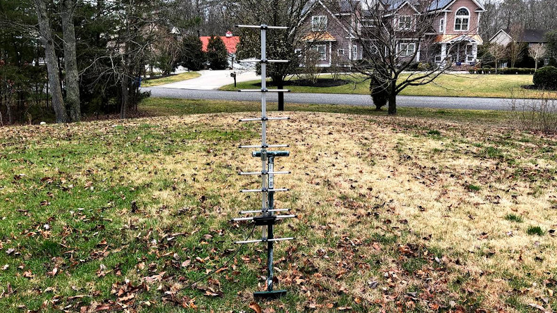
In a bid to test its efficiency at bouncing off the troposphere in normal conditions, [Inductive Twig] hooked up a HamShield 70cm LoRa shield to an 80W power amplifier and a high-gain Yagi antenna pointing directly upwards mounted with ingenuity on a spade, and drove around looking at the received result. With an effective radiated power of 1500W this wasn’t your normal LoRa, instead being operated with LoRa as an amateur radio mode.
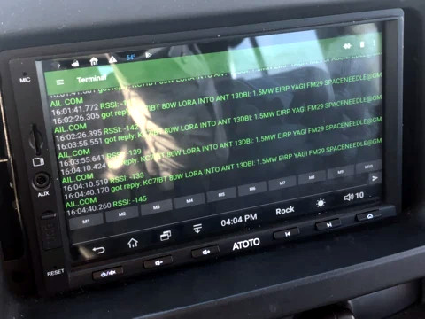 For those not familiar with radio propagation, radio waves bounce off some surprising things. In this case the aim was to bounce them off the troposphere, but while radio amateurs and LoRa distance chasers wait until weather conditions deliver a so-called “lift” in which the troposphere is especially reflective, here the experiment was performed under normal flat conditions. The result characterizes LoRa’s possibilities for everyday extreme-range mode rather than chasing records, and in that there were some interesting results. The reflected signal was receivable in bursts with low but consistent signal strength, with the limiting factor during the test as that they ran out of land upon which to drive in the southernmost peninsula of New Jersey. We’ve heard of War-Driving for open WiFi… does this car dashboard setup count as LoRa-Driving?
LoRa is designed as a protocol tolerant of low signal levels and some packet loss, so this experiment is an interesting demonstration of its possibilities when used at higher powers under a licensed transmission. It shouldn’t be possible to use the 70cm band for reliable tropospheric propagation under non-lift conditions, but this shows that it can be done. Meanwhile, take a look at a previous attempt to push LoRa using a balloon.


The brute force approach to tropospheric scatter commuications was what Western Electric did in Alaska in the 1950s, to provide datalinks for the DEW Line sites that guarded our northwestern border, as well as civilian telephone service, with their White Alice network, but they used the 33 cm band. The longer-range sites were up to 150 miles apart and had huge “billboard” reflectors for their separate transmit and receive antennas. Each site had four antennas, two facing each of the adjacent sites in the chain. It was kind of expensive to build and maintain, and these were eventually (late 1970s) replaced with satellite ground stations.
This map, http://rammstein.dfmk.hu/~s200/tropo.html#alice, shows the White Alice network as well as a number of other networks that used tropo scatter to connect remote locations.
“This map, http://rammstein.dfmk.hu/~s200/tropo.html#alice, shows the White Alice network as well as a number of other networks that used tropo scatter to connect remote locations.”
Wow! Excellent site! Wondering what the interpolated image resolution is in near real time with all the sites… plus the ability to hack in allies and other sites not only on the ground data? Amazing the capabilities now days in more than just the optical and IR range from space to add. Probably so obvious, that’s why RTK GPS came out main stream.
Wondering if able to image the range of molecular energies spectroscopy frequency ranges?
I recall back in 2000 research China had been working on to create a RADAR that was totally passive in regards to only detecting disturbances in the existing infrastructure transmission/emissions.
Use to hike up to the site on Adak. Have several close up pix.
Neat, just skimmed through the datasheet for the SX1276 since reads the module is using a “Semtech SX1276 with amplifier and RF shielding”
https://cdn-shop.adafruit.com/product-files/3179/sx1276_77_78_79.pdf
Was also reading about the SI4463? since Google popped up in the search term and I forget off hand where I was recently reading about:
https://www.silabs.com/documents/public/data-sheets/Si4464-63-61-60.pdf
Interesting… I invested in a bunch of Si4432’s (RF22 rebranded?) to play with since so cheap:
https://www.silabs.com/documents/public/data-sheets/Si4430-31-32.pdf
Any other rebranded SX or Si versions out there I’m not aware of? Would be an interesting table to have the chips specs itemized on.
Would be awesome to hack into the RF Block of the latest generation of GPS modules and mod or bypass the Digital Block… man, those look really sensitive and seems like can be an interesting detector or receiver with a front end mixer mixing (maybe BPF filtered) into the Rx pin.
More like RF22 is a branded module using Si4432.
As for others the Texas Instruments CC1101 series is also quite chepa and common and Si4463 is also quite common in addition to the Si4432.
As for More generic SX modules and chips, none exist as SEMTEC holds the LoRa patents. There is a licensed chip from Microchip in addition ot SEMTEC SX-seires stuff but that’s about it.
“More like RF22 is a branded module using Si4432.”
Good call, thanks, that’s what I meant. Sometimes the mind and finger(s)… with that return key effect have a mind of their own.
Tropospheric scattering has a skip zone close to the transmitter. Probably would have had better results a few hundred miles away. Also 70 cm is not a good band for reflection. Better to use a much longer wavelength.
With the antenna pointed straight up the skip zone should be small. I think the issue was more the monopole on his car having a null towards the sky. Probably he was receiving a reflection of the scattered signal.
Still, impressive. I would have thought on 440MHz the scattered power would be too low.
Yes, you’re right. What they are doing is NVIS (Near Vertical Incidence Skywave).
https://en.wikipedia.org/wiki/Near_vertical_incidence_skywave
Best frequencies for this are very low (3 or 7 MHz)
I did something similar about three years ago with LoRa and troposcatter (https://faydrus.wordpress.com/2018/10/20/my-tapr-dcc-2018-paper-presentation/).
Some things about troposcatter:
1. It’s a not a “skip”. It’s more like shining a flashlight through cloudy Jell-O in that most of the light just passes through, but some of it gets scattered in other directions. Compared to ionospheric skip, it is a much weaker effect. You should expect at least a 60dB path loss just from the troposcatter itself, on top of any other path losses.
2. Microwave frequencies in the 2-4GHz range are usually what’s used for commercial troposcatter systems, so even higher frequencies work well (and may even work better).
3. It doesn’t really have a “skip zone” close to the transmitter. The main dead spots I saw nearby were most likely due to the extremely directional signal my ~15dBi Yagi antenna was transmitting.
4. Several 100’s of miles is *very* good for troposcatter. Using realistic equipment, you’re probably more likely to see 100-200 miles range on 70cm.
5. Radio Mobile Online (https://www.ve2dbe.com/rmonline_s.asp) will account for troposcatter (as well as knife-edge diffraction) in its coverage maps and path calculations.
This is illegal. Amateurs are allowed 10W PEP maximum with spread spectrum.
How about a link to the portion of FCC Part 97 that shows this? You have made me curious. (It’s been a long time since I studied the power limit laws, since I always run barefoot.)
97.313(j) https://www.law.cornell.edu/cfr/text/47/97.313
Thanks!
Power limits removed a few years ago. Part 97.311 is practically empty compared to years past. The FCC “always” plays games with constant rule changes when a technology is new or obscure, then gradually falls back toward plain old 97.313 rules (1500 watts, etc). Since the 80s there’s been more SS rule changes than I can remember. I remember in the 80s there were specific spreading formulae and you could only use some small slice of 2M or something weird like that. Before that it took an experimenters license. Rules now in 2020 are almost entirely wide open. At various other years there were obscure spreading formulae limits, strange CW ID requirements, weird logging requirements, strange band plan limits, all that stuff is essentially gone now.
Here’s a real puzzler. On the commercial side a company doing OFDM packet radio, WiLan or something like that, historically tried to get 15.247 certification as a 902 mhz band spread spectrum device and the FCC engineers denied them because their OFDM wasn’t spread spectrum wide enough compared to narrowband rtty, to paraphrase and probably misquote our friendly FCC overlords. So depending on the exact protocol and software and drivers that OP used, the definition of what EE textbooks call SS vs what FCC bureaucrats call SS is, at least historically, not in complete agreement. Although in spirit, yeah, OP was probably transmitting SS. But 97.311 being practically empty now a days means none of this matters anyway.
73
OFDM isn’t really spread spectrum though. Did they have some sort of FHSS as well?
I’ve looked at the FCC rules for ISM band operation in 915MHz, and it’s not enough to be “spread spectrum”. To comply, there’s also a bunch of rules regarding dwell time in a given channel, minimum number of channels, bandwidth, etc.
Ooops they moved it out of 97.311 to 97.313(j) “No station may transmit with a transmitter output exceeding 10 W PEP when the station is transmitting a SS emission type.”
Now time for a fun discussion of what PEP measurement means vs actual SS signal waveforms vs the amp has a limit of 80W but that doesn’t mean the PEP signal at the output exceeds 10 W.
OP used a nice DMR amp and its web page claims that it requires 5 watts in to get a likely well compressed 80 watts out, under ideal conditions with the best power supply and best antenna match etc. OPs LORA shield outputs 1 watt on its best day and ideal conditions with no filtering. Using miracle zero decibel cables that don’t exist and all the stars aligning perfectly, OP might in theory have transmitted at a theoretical 16 watts PEP, but in practice I think OP designed a system that runs right at the legal limit, which is good design work.
Note that ideal zero feed line loss 10 watts transmitter output to 1500 ERP is only a 21 dB power gain. Having done weak signal work on 70cm I would not call 9 elements a “high gain antenna”, medium to low at most. 11 elements will get you 17 dBi. A 15 wavelength antenna like the popular M2 product would easily give 22 dBi gain which would be a completely honest 1500 watt ERP even with short lossy feed line. The turning radius of that monster is nineteen feet a bit larger than ops antenna. I owned its much smaller brother and that was a good antenna. Aside from the ramble the summary is that low gain antenna OP used plus real world feedline losses would provide handwavy “somewhat more than 500 W ERP” rather than around 1500 W ERP but a couple dB in the TX will only result in a couple dB in the RX SNR which isn’t going to significantly modify OPs experimental results anyway.
Well whatever. 73 and best of luck
I thought you were wrong, but §97.313(j) does clearly state maximum PEP (peak envelope power) for SS (spread spectrum) emissions is 10W.
IMHO, it’s a welcome improvement over the previous FCC SS rules, which required Automatic Power Control (APC).
It’s fairly easy, though, to get a Special Temporary Authorization (STA) for six months to exceed these rules. I did exactly that when I did my LoRa 70cm troposcatter experiments, and those involved me pointing my 15dBi Yagi over Kirtland Air Force Base.
My band plan sheet says 1500w PEP maxim power for UHF
Have there been any attempts to bounce a LoRa signal off the moon?
The EME path attenuation at the lowest frequency that current LoRa devices operate (137MHz) at the moons Perigee is about 256 dB and at the highest frequency (1.02 GHz) is about 275 dB at the moons Apogee.
So my guess would be no, it is just not going to work with LoRa. The protocol does not have a long enough integration time.
Well technically it is possible with enough gain, like if you had access to Arecibo with an Antenna gain of 61 dBi it is possible. It could make an interesting marketing stunt for semtech.
There are two LoRa Calculators extremly well hidden on the semtech website one for the SX1272 chip and one for the SX1261 chip, but in reality if you play with both calculators the numbers they generate are almost the exact same, and could probably be used for all other chips from that vendor (the owner of the LoRa patent).
For maximum range (link budget @ 0dBm TX power would be ~150dB) you want the highest spreading factor (12), the lowest bandwidth (7.81Hz) and highest coding rate (4/8). And if you wanted maximum throughput (link budget @ 0dBm TX power would be ~113dB) it would be the lowest spreading factor (6), the highest bandwidth (500kHz) and lowest coding rate(4/5).
There is no mentioned in the linked article of what settings were used on the SX1276 in the HamShield, so I dug through the source code (LARPS_Beacon.ino and RH_RF95.cpp) and the default, if unchanged, is 125kHz bandwidth, a Coding Rate of 4/5 and a spreading factor of 7 which at 0dBm TX power would be a link budget of ~123dB (Or at a TX power of 63dBm, a link budget of 186 dB).
Im using 7.8KHz/SF7 over a 8KM link with the SX1278/RFM96.. Very good but the frequency drift over temperature needs to be compensated for. The narrow BW Phy seems to be a bit more of a polite use of the spectrum.
Anyone tried the SX126X radios? TCXO?
P
Nice use of an Android head unit.
Huh…I used to do heavy tropo way back in my army days. Good old 514th Signal. Also helped to field a commercial tropo package variant for the SNAP when I contracted in Afghanistan. It’s an awful lot of fun, and great if you have a mountain in the way, but as I recall, it’s super finicky to set up and prone to outages exactly when you need it up the most.
I setup a LoRa base station at my house, using arduino, and hamshield, connected via usb to a raspberry pi for remote control. I used 1/2” hardline to feed an antenna (home made folded dipole) on my roof, with a 440-450 mhz pass band filter in line. The remote station was in my van with laptop/cell card to remote into the pi at home, and similar filter/folded dipole. Managed to send text msgs back/forth over 9 miles, from a location smack in the middle of a massive urban city, to my house in the suburbs, at less than 1 watt. I was blown away! I have been a ham for years, and getting a 70cm simplex signal through all those bldgs and freeways at only 1 watt!? Think downtown LA business district on the street corner… Had to use a smaller bandwidth, and spread factor of 12, but it worked. Next tests will be with 20 watt amplifier, and yagis on both ends.