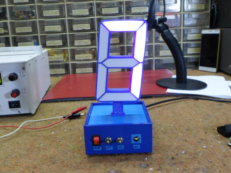
Have you ever looked at the time, and then had to look again because it just didn’t register? This phenomenon seems more prevalent with phone timepieces, but it’s been known to happen with standard wall clocks, too. This latest offering in a stream of unusual clocks fashioned by [mircemk] solves that problem by forcing the viewer to pay attention as the time flashes by in a series of single digits, separated by a hyphen.
Inside the boxy blue base is an Arduino Nano, a DS3231 real-time clock module, and a perfboard full of transistors for switching the LED strips inside the segments. There’s an LED on the front that blinks the seconds, and honestly, we’re kind of on the fence about this part. It would be nice if it faded in and out, or was otherwise a little less distracting, but it did grow on us as we watched the demo.
We love the way this clock celebrates the seven-segment display, and only wish it were much bigger. The STLs and code are available if you want to make one, though they only cover the 7-segment part — the base is made of foam board. Check out the demo and build video after the break.
Would you rather hear the time go by in gentle chimes? Here’s chime clock that uses old hard drive actuators.


Nice and simple.
Just one suggestion, he should have used RGB LEDs for this project, then he could have used red for hours, green for minutes and blue for seconds, harder to implement but simpler to read. (Unless you’re colourblind.)
With two digits he could display all 3 at the same time, forcing one to parse the digits from the combined colors. I wonder if the brain would eventually get as fast reading that as an analog clock
Interesting twist. If you want to make an annoying clock, you might as well go full throttle.
The wiring diagram shows current limit resistors between the nano and the drive transistors and no current limiting resistors on the segments.
I would have looked at using a ULC2803
ULN2803a
The LED strips they used have resistors already on them. Additional ones are not required.
the image in the section ‘Step 4: Shematic, Code and 3D Printing Parts’ does not show those resistors. by not showing all of the components in the drawing, that incomplete circuit may mislead or concern a few people here and there.
That schematic is complete and shows all the required parts and their connections. Following your logic the diagram should also show the resistors already included in the clock and microcontroller modules. You must know the part called out for the LEDs, “SMD5050 Led strip” is commonly known not to require external resistors.