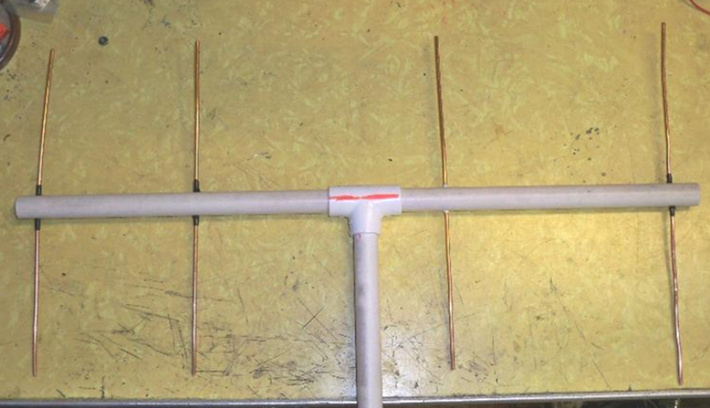
If you are looking for a fun project while you are cooped up and you have some spare coathangers, why not try this 4-element Yagi antenna (PDF)? [Pete N8PR] showed it off at his local ham radio club and it looked like something good for a lazy afternoon. If you aren’t a ham, you could adjust it all for a different VHF or UHF frequency.
For the boom, [Pete] mentions you can use wood, but it isn’t weather resistant. He chose half-inch PVC pipe. He also offers you a choice of material for the elements: #8 wire, welding rod, or — our favorite — coat hangers.
This is a big upgrade from a simple dipole or a vertical made from coax. The yagi should have about 8 dBi gain in the direction it is pointing. The center of the boom doesn’t have any elements, so that simplifies mounting. The insulating boom also makes mounting the driven element a breeze.
If you use the coat hangers, we’ve heard an easy way to get them very straight is to put one end on a vise and the other end in a drill chuck (see the video below). The method will weaken the wire, but the elements won’t have much stress. If it worries you, just go slow on the drill and you might consider annealing the wire with a torch afterward.
It would be easy to make this portable like some other designs we’ve seen. If you want the history and theory behind the venerable yagi antenna, you’ll want to revisit this post.


I have had luck straightening coat hangers for antennas by manually making it as straight as possible by hand, then place between two 2×6 boards and stand on top of them and roll the wire in between the board.
If you use brazing rod (brass) you get a better radiator because steel is not that great for RF emissions and the wire is very straight and stiff. It also solders well when you go to attach the coax or other feedline. You can make a yagi for directional use, or a ground plane antenna using a PL connector and 5 wires. Solder a 19 inch radiator to the center of the PL, then bend an eye in one end of the four ground plane wires and attach them to the corners of the PL using small machine screws/nuts/lockwashers. Bend the 4 ground plane wires down 45 degrees. Take a 10 foot PVC pipe and run the coax through it and out the end. Screw the coax connector onto the PL and pull the coax down until the antenna rests on the open end of the pipe. Use the pipe to attach to another mast vertically and you have an omni directional ground plane antenna. (all the wires start out 19 inches long, and to adjust SWR you may have to cut off the end of the radiator. Wrap the ends of the wires with 3M electrical splicing tape to be safe.
He says it’s for 2m, as is the lengths given, but his pictures are either for high UHF TV or 33cm
Derp it’s half wave low UHF TV or 70cm
If you want to make a 2m one, there are abundant plans on the net. Basically VHF/UHF Yagi for amateur radio start with only 3 elements attached to the beam.
+1 I hadn’t seen that “trick” before to straighten wire, though I’ve used a similar trick to combine Christmas light strings into a single string.
I’ve used a drill to twist multiple strands of magnet wire for use when winding a toroidal transformer. I’ve never seen it used to straighten wire, frankly, I’d be a little concerned about the material properties of the resulting piece. I suppose it wouldn’t matter much in the low-stress case of this antenna though.
as long as you dont break it the work hardening might even be a benefit for an antenna
Yes I want to say it would be more springy, so bounce back rather than bend when the fat pigeon sits on it.
I was house sitting for my father and he had the satellite TV cut off while he was away(thanks dad) I found one of those metal frame real estate signs and said Hey that looks about the right dimensions. Got rid of the rust, Made some adjustments to it, soldered on some rg58 and a mount for the back of dish and used the sats cable. He laughed when he got back, but it got a bunch of channels 60 miles from most of the stations! He got a premade antenna and replaced mine and only got half the channels.
You should write this up, include photos of a mock up, throw in some math, and submit it to hackaday. Instant cred!
Heh yeah, I don’t know if it’s a case of “almost anything is better than the cheaper store bought antennas” or what, I know my “minimum viable TV antenna” tends to outperform any set top indoor antenna. We’re at the bottom of the “all image sites suck” cycle at the moment, so no pic…
Minimum viable TV antenna, get aluminum soda can, 2 screws, coax TV antenna wire, knife, scissors, screwdriver, lump of wood, about 5 inches of a 2×4 is fine, or bit of particle board or whatever will hold a screw, bit off the woodpile with a flat face even.
Take can, guess a line about 75 degrees, (halfway between 60 and 90, or guess 45 and third that to 90) from top to bottom of can, gash down that line with the knife, then cut around top and bottom with scissors, and you’ve got a parallelogram, mark about 1 cm down each of the short sides at opposite ends, then rule a line that goes almost corner to corner, but stops at the 1cm marks. Cut along that line, giving you two long trapezoids, or tall hopefully equilateralish triangles with a cut off point… Now flatten these out as best you can, maybe score a line up the middle of them or kink them so they don’t curl up. Near the 1cm end, poke a hole in each.. roughen up round the hole to expose bare aluminum, strip end of coax, or use a 300 to 75 ohm balun to be fancy, bend Us in the ends of the wires, screw down your two trapezoids with about 2.5cm between the ends, fasten the wires under screws as you tighten them down, arrange your two trapezoids so they are in line to each other as you fasten. It’ll be something like a fat figure 8 pattern so aim it at best right-ish angle to the two biggest cities, plug into your TV and retune.
However, if you want to get serious about making TV antennas, 4 bay bowties or hovermans perform much better. The antenna design in article is probably pretty good for directional reception with modified lengths (helps if you’ve got stuff on the same channel at different compass points)
By the way, that’s the exact reason why I kinda slid into “make a TV antenna from anything you can find” the number of times I’ve been duped into house/baby/dog/grandma sitting for a few days and the cable just got cut off, or they’re waiting for the sat installer, or they just gave 500 DVD collection to goodwill last week, or they “forgot” netflix password, or whatever is unreal.
I end up lugging in a huge bag these days with ALL essentials, whereupon they say “well you didn’t need X we’ve got plenty” however when I don’t it’s “We gave up coffee last month”, “The dog chewed all the chargers”, “We ran out and forgot to get some” .. .. ..
Do you bend a drill bit to grip it in the chuck better? Why the bend at all on either end? If the wire in the middle is bent sharply it’s already partly broken un-bend it more and it breaks. Hangers are steel and have little life outdoors. Nothing in the video about antennae construction. A heavy board on the bench top or pavement and after several presses roll to flatten completely is easier if needed at all.
Sadly wire coat hangers are a threatened species. I don;t think there is anything that can be done to preserve them, they are just dying out.
I did spot this happening several years ago and preserved a box full like a good environmentalist.
Find a friend that has to wear uniforms to work and you’ll find an endless supply of wire hangers.
Plastic coat hangers give you better common mode rejection ratio. Also, far greater signal attenuation.
and they are much better in rough conditions as they don’t rust..
makes you wonder why no one has 3d printed antennas
100% signal attenuation? Zero noise reception as well.
signal to noise ratio also off the chart
This actually concerned me at one time, since I use coat-hanger wire often. Then I found a box of wire coat hangers at a second-hand store that will easily last my lifetime, and probably my kids too. It’s a big, heavy box.
What is this “spare coathangers” thou dost enscribe, William sir?
Forsuch, my domicle hast naught.
Find a friend that has to wear uniforms to work and you’ll have an endless supply of wire hangers.
Find a friend that has to wear uniforms to work and you’ll have an endless supply of wire hangers.
Has anybody worked out the loss due to the skin depth and resistivity of steel at the frequencies of interest? Compared to, say, just using a length of copper or aluminum? Hint: you don’t want to use nickel-plated stuff for this.
It’s not that bad if you use smooth, clean steel. But if you chuck it in your vise/drill jig to straighten it out, you’ve not got a smooth wire when you’re done. Then if it’s bare steel out in the weather, you’ve got radar absorbing material covering it after a while. That’s why aluminum is used for most antennas.
Indoors, steel is fine. Just roll it between a board and the floor to straighten it.
OK, so I had to go find out. According to the skin depth and resistivity calculator at owenduffy.net/calc/SkinDepth.htm, at 450 MHz a copper wire 3 mm in diameter has a skin depth of 3.1 microns and a resistivity 244 times its DC value. An iron wire the same diameter has a skin depth of 0.53 microns and a resistivity 1414 times its DC value (which is itself 6x the resistivity of copper).
Net result: losses in a coathanger wire antenna are 35 times the loss in a copper wire one. I think it’s going to show a good SWR over a wide band… Because it’s going to make a not bad dummy load.
Nice design! It may benefit from an impedance match, such as a hairpin wire match at the feedpoint.
The joint in the center of the driven element weakens the whole thing. Better to make it continuous, and run another piece of wire out to a feed point. Find a good feed point somehow (using received signal) and solder it there.
Concerning straigthenig wire, have a look at this article:
https://hackaday.com/2018/10/14/diy-wire-bender-gets-wires-all-bent-into-shape/
This is how wire straigthenig works in industrial applications.
Its annoying if people use inches instead of the metric system. It’s 2020, I’m wtf?🤦🏻♂️
*I mean wtf?🤦🏻♂️
I’m in the US .. and here we use the good ol’ fractional inch system. I can manually find 5/16 of the length of something quicker than you can find 0.3 of the same length!
Thin wires aren’t sturdy and are very narrowband. I like to use old copper water pipes. No rust, easy to solder.
Link for PDF is dead. The resource has moved to: http://www.dcarc.club/presentations/2016%20N8PR%202%20Meter%204El%20Yagi.pdf