The humble ATmega328 microcontroller, usually packaged as an Arduino Uno, is the gateway drug for millions of people into the world of electronics and embedded programming. Some people just can’t pass up the challenge of seeing how far they can push the old workhorse, and it looks like [Guido PE1NNZ] is one of those. He has managed to implement a software-defined SSB ham radio transceiver for the HF bands on the ATMega328, and it looks like the project is going places.
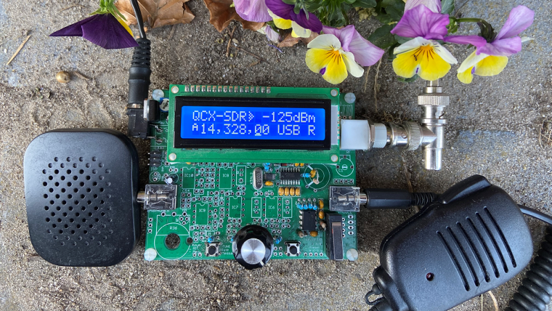
The radio started life as a QRP Labs QCX, a $49 single-band CW (morse code) HF transceiver kit that is already one of the cheapest ways to get on the HF bands. [Guido] reduced the part count of the radio by about 50%, implementing much of the signal processing digitally on the ATmega328. On the transmitter side, the SSB signal is generated by making slight frequency changes to a Si5351 clock generator using 800kbit/s I2C, and controlling a very efficient class-E RF power amplifier with PWM for about 5W of output power. The increased efficiency means that there is no need for the bulky heat sink usually seen on SSB radios. The radio is continuously tunable from 80m to 10m (3.5 Mhz – 30 Mhz), but it does require plugging in a different low pass filters for each band.
The modified QCX is named QCX-SSB, but the project is rapidly evolving with [Guido] and a few other working to turn it into a completely new radio, called the µSDX. Go drop in at the discussion group to stay up to date. If you want to build your own, the easiest way at the moment is to get a QCX kit, and build it using the instruction on the QCX-SSB Github repo. Take a look at the overview below by [Manuel DL2MAN]. However, the project is rapidly evolving, and it seems very likely that it will soon outgrow its QCX base and the ATmega328 powering it.
This project could greatly reduce the technical and financial barrier of entry for new hams into the HF bands, and we will definitely be keeping a very close eye on it. If you want to get started with just a receiver, check out this multi-band SSB capable receiver based on the Silicon Labs Si4735.


Thank you for posting this! This is a very fun project. I myself recently built such a radio from one of the last QCX kits of hte original style. I currently have it running JS8. I’ve made several JS8 and FT8 contacts with it, as well as a SSB contact. Pictures and more on my site:
https://miscdotgeek.com/ssb-and-digital-with-a-qcx/
So nice to see projects for RF outside of 430 & 24k Mhz…
Honestly at only 5 watts the antenna is probably a good enough filter and you don’t need to low pass filters at all
I see your point, but its got a class-E RF amp stage so there is some considerable amount of harmonics in the emitted spectrum.. and in any case, ham radio equipment specifications should adhere to the ITU recommendations.
Wrong, a HF antenna doess not behave as a filter like a VHF-SHF antenna, 5W is enough to steralise a large part of spectrum and gives you worldwide coverage. Most spurious fall in other ham bands but this kind of behaviour is not accepted among hams and also not by the authorities.
No its not, a HF antenna barely filters.
While the picture doesn’t show a low pass filter, one is definitely needed and is indeed implemented by anyone making this radio. In my own project I use one, and plan to have multiple switched LPF’s (See my link in the first comment).
He does it with an offboard low pass filter. He figured a bunch of separate low pass filters, one for each band, was a better method than putting the filters on the main PCB. It’s probably under those flowers connected to the antenna jack.
For the case of FCC specs, in this frequency range and power level, -43dBc is specified. It may be more restricted in other countries. As I have worked with multiple Class C/E/F amplifiers, I cannot recall unfiltered levels better than -17dBc due to non-linearity. So the filter is necessary, and this one in the schematic should work. Also, note that the usual Class E calls for a series-tuned L-C output (at C29), so as to maintain the proper relationship between Drain Voltage verses Current. Usually this topology results in Class C or Class-C mixed mode.
So, Yes. LPF.
And some people are afraid to move on (also to SMT in general)…
I hate to admit it, but I’m one of those who don’t want to deal with SMT stuff. But I’m trying to get into the new stuff. I bought a cell phone repair station hoping it would help me deal with SMT components now or in the future. SMT has been around for 25 years or so. It’s not new technology anymore, so most older hams should get at least get familiar with it.This is a great time to be in amateur radio. Technology is half of what ham radio really is. Hams used to have things going on that were way ahead of what was coming out ot the factory. Components like this make ham radio what it used to be. Building stuff from scratch. But now it’s more affordable than ever.
25 years, and the rest, was just looking at a 1978 datasheet that had the IC offered in a surface mount package. We wouldn’t have had the digital watch and calculator boom without it, though some were a bit of a mix. It was in all sorts of mainstream stuff by the 90s though.
I think if you go right back, it was an offshoot of those medium scale integration modules of the late 60s through 70s, where dies and other components were mounted to a board in a module then sealed up.
I avoided SMT for quite a while, though I had all the tools to use it. I finally bit the bullet on a Soda Pop II kit Steve Weber found in his inventory, and I’m having a BLAST building the thing. I use an I-Extruder for dispensing solder paste, and a hot air reflow station to do the soldering. I HAVE a programmable reflow hot plate (ReflowR), but haven’t used it yet, as I tend to build in sections and the hot air pencil is far more useful for that.
A microscope also helps a lot. I have an electronic one with its own screen that’s quite good. Some decent tweezers, and a lighted magnifier for the stuff too small to see clearly but too big for the microscope, and it’s off to the races! Lots of fun!
I find it questionable that a credible direct down-conversion HF SDR receiver can be built with an 8-bit RISC micro-controller [ATMega328P/PU] with very little RAM, (typically) 2-clock cycles per instruction running at 16 MHz, and using the limited on-die 10-bit A/D converters. But that’s what the schematic and block diagram for this radio shows:
https://raw.githubusercontent.com/threeme3/QCX-SSB/master/block.png
https://raw.githubusercontent.com/threeme3/QCX-SSB/master/schematic.png
So perhaps miracles do happen! Nice work…
Also, a good commutating direct down-conversion receiver design should employ some form of antenna input isolation (e.g., a pre-amplifier or buffer) for the following two main reasons:
1. The gain and bandwidth of a commutating direct down-conversion receiver is dependent on the antenna’s impedance and how well it is matched to the input of the quadrature mixer.
2. If not carefully designed and constructed, unbuffered commutating quadrature direct down-converters are notorious for radiating the mixer’s clock frequency out the antenna port when receiving.
The receiver design in the radio being presented here has no pre-amplifier (or any other form of isolation) between the antenna port and mixer input.
Issue-1 above is discussed in some detail in Part-1 of Gerald Youngblood’s [AC5OG] 2002 QEX 4-Part treatise entitled: “A Software-Defined Radio for the Masses”[1]. All 4-Parts of Youngblood’s paper may be freely downloaded here:
Ref.-1, http://www.arrl.org/software-defined-radio
KC1CCG says, Great little project. Just in time for hunkering down I bought the IC7300 and it is amazing. But, I still appreciate QRP on CW and skill vs brute force. No, antennas do very little filtering for harmonics. A good thing or all our multi band antennas wouldn’t work. Although 5 Watts isn’t going to throw up much harmonic QRM we want to keep as clean as possible. And a filter isn’t rocket science….its network analysis. 73 and pray for sunspots!
Cool project. However, why not use a cheap Arduino module for the ATMega328 instead of a discrete MCU. Motherboards with cheap, standardized, off-the-shelf modules mounted as daughterboards are the way to go whenever possible, IMO.
This article “sticks an Arduino in it” but it does not ruin a salvageable cool looking vintage radio. Double thumbs up!
Cool project to kill the time until QRPLabs finishes the QSX.
I dont think the QSX will ever see the light of day. I’m with Guido and Manuel and hope they migrate to the new 4 dollar RP2040 Pico and ditch the venerable but obsolete 328. The Pico boasts 125 MHZ clock and 12 bit ADC, with 2 cores to boot. I’m trying to port Guido’s code as we speak.
This is on the repository and is a very good guide.
https://github.com/threeme3/QCX-SSB/blob/master/QCX-SSB_assembly_Rev-5.pdf
Will it be possible to buy a ready-made one in the future?
is it possible to change the program arduino board uno with a nano ,then i don’t have to buy a uno
perhaps the uno is easier because you can plug in a 328 in th uno board and progran it direct