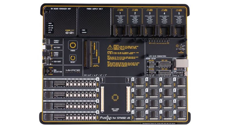
Clearly profiling itself as the Lamborghini or Ferrari of the STM32 development board world, MikroElektronika’s current (8th) revision of their Fusion development board was released last year with support for not only flashing but also debugging the attached STM32 MCU via the onboard WiFi module. The Serbian company’s pricing for the bare board without MCU modules or any other peripherals appears to be around 300 USD/Euro. Additional MCU boards cost between $28 – $60 each.
As the official product page explains, the board is combined with the CodeGrip software to manage the board either via USB-C (driver-free) – which also allows one to configure the WiFi option – and via WiFi. Peripheral boards are added via the 5 onboard MikroBUS expansion slots, either with existing boards, or custom MikroBUS boards. The power supply is also onboard, powered via USB, a barrel jack connector, or an external battery.
The use of WiFi to connect to the board would allow for it to be easily managed and debugged when it’s in a less convenient location than one’s desk, which would seem like a major boon.
Obviously it’s not a cheap board, and the MCU cards each cost about as much as a Nucleo or Discovery board from ST would cost, making it hard to justify purchasing it for anything but a professional environment. However, the tantalizing thing here is probably that so much of the design details are available, from the expansion bus to the pin-out and schematic of the MCU cards (STM32F767ZG version).
The MCU cards use the Hirose FX10A-168S-SV and FX10A-168P-SV(71) connectors, all readily available. This opens the possibility of developing compatible MCU cards. An MCU card template project can for example be found here.


I can see some benefit to debugging over wifi, but I don’t see myself using an off-the-shelf development board inside a on-site application where I can’t just use a regular USB cable.
A more practical idea would be to have a wifi-enabled JTAG debugger that you could attach to any JTAG-equipped board, and then use that to debug at a distance. That way, you can use it with your own production/prototype boards.
you mean something like the ctxLink?
https://www.crowdsupply.com/sid-price/ctxlink
There is Wifi-JTAG:
https://github.com/emard/wifi_jtag
But:
“JTAG upload is slow because OpenOCD creates network traffic with short packets of 1-3 bytes sending to and from WiFi-JTAG.”
So there is some improvements to be made there.
Something like https://www.crowdsupply.com/sid-price/ctxlink (a wifi enabled blackmagicprobe with lipo battery and wide voltage range support) perhaps?
Got mine a couple of weeks ago and it seems to do the job.
Interesting, this is black magic probe based, I’ve seen a fork of black magic probe that also runs on the popular ESP wifi microcontroller. I wonder how they compare.
Probably little difference in terms of software features, since they both leverage BMP. ctxLink has the extra hardware for lipo battery and charging support, proper signal isolation, and the ability to run either wireless or USB. But you can cheaply integrate an 8266 onto a project board and permanently give it wireless debug/uart capabilities.
Build your own one with a ESP32 or ESP8266:
https://github.com/walmis/blackmagic-espidf
I was looking for a fork of BMP that did WiFi and just founda new one instead, in the link above. Looks very promising, maybe HaD should do an article on it.
Looks very promising, I’ll have to give this a try when my next esp8266 boards eventually arrive.
Can’t believe it only has 3 stars!
How is this article any different from a big advertisement for some expensive, big and unwieldy commercial development platform?
Maybe it’s just me, but I never understood those big boards with nothing but buttons and connectors you do not need for your own project. As far as I can remember MicroElectronica has always had the biggest (but least useful) development boards.
I do understand development boards with specialized hardware such as for example motor controllers.
I would prefer a USD3 Blue Pill with an equally priced ST-Link V2 clone over this development board.
My first thought when I read the title of this project was that some combination of “Black Magic Probe” firmware ported to an ESP8266 or ESP32 could be useful. Partially because my development board is not always on my desk, but also because of galvanic Isolation. Some of my projects are connected to mains voltage, and also need to be during development such as for example phase controlled light dimmers. So I’m glad to see such projects are already available.
———
About STM32 development boards…
STM32 is quite popular in Chinese products.
Some time ago there was a Hackaday project of a re-purposed “transistor tester” (with AVR uC) here on hackaday, used for some in car radio display. The same can be done with Chinese STM32 boards.
DPS5005 (and other power supplies) have a STM32. The smaller / older version (I think DP3603) has just a few 7-segment displays, but also an STM32F100 and is still a quite capable power supply which begs to be used with custom firmware (add some encoders, and remote control)
Search chinese websites for “FX2N” and you get lots of cheap PLC boards with an STM32F103 on them, and they even have break-out pads for re-programming the STM32.
Even though I do not have a 3D printer, I recently bought an add-on module for a 3D printer with a 3.5″ TFT and an STM32 on it’s back. Firmware is Open Source and available from GitHub. If you take a look at the “Nextion” TFT modules, you see they also have an STM32 on their back. You can either use them as intended via a command interface, or flash your own project software directly into the STM32.
Addition:
I just noticed you have to cough up an extra USD80 just for the WiFi license.
https://www.mikroe.com/codegrip-wifi-license
And the license only works for one board. Not only expensive, but also a hassle to deal with.
On the plus side:
Think of the amount of money you save if you do not buy into this stuff.
Now multiply this with 10 and you save even more money if you do not buy it :)
About 10 minutes ago I placed another order for 10 Blue Pill boards. Total price was EUR 16.
No hassle with license keys either.
I’m trying to imagine how to make use of 200+ pin microcontroller on the board above and try to use all those pins via the breakout connectors in the lower right corner, My imagination shows me a horror movie nightmare worse than the breadboard mess of big projects.
Just as with the use of the big Hirose connectors. These do not add anything for end users. The connectors are not easier to solder than the uC itself, and the plugin boards do not have more than the connectors, the uC and a hand full of passives. The only thing they do is add bulk to a project.
I’m also afraid of tolerance problems if you try to make boards with 2 of these 168 pin connectors.
I do want to be positive, but it’s hard for this product.
So if anyone who uses big boards as these in a useful way, then please post some links.
Normally I see these “made for professional environments” and think “what professional would actually use that?” but this was compelling
WiFi programming and development was not a huge draw but a nice convenience thing after it’s set up
Im most interested in the swappable MCU cards and opening up the ability to actually do early dev on something in the near family of your target without the annoying wiring mess or the need to have 20 generic dev boards
Ill definitely keep it in mind
We did recently blow $4k on an FPGA dev board everyone will just be too scared to actually use
I think it is aimed more at the educational market – tech colleges etc.
If I were to blow this kind of money on a dev-board (I am not), I would probably just get the official xyz-EVAL boards from ST instead. Normally, I’d be happy enough with a much cheaper xyz-DISCOVERY board instead; they still usually have at least a few things to play with e.g. a display, maybe some audio and sensor(s) etc. but still at a reasonable price. And then there’re the very cheap, very bare-bones Nucleo-boards of course.
For me, it’s more than enough to start small with the cheap boards to get to know a particular MCU; or as someone said, often a really, really dirt-cheap Bluepill would suffice.
Then I’d much rather spend some time and resources on maybe doing the project-specific board instead, and get a fully customized board 2 weeks later from the cheap Chinese board shops. Still much cheaper than this beast.
And by the time the custom HW arrives, hopefully some bring-up FW is already spinning and tested on the cheap generic Nucleo/Discovery boards
You know why it is 300 a pop ? It has premium features. Power supply ? Premium power supply. Premium SomethingBUS, premium keine Ahnung was. It reads like one of those ~300 bucks PC MoBos.
The PCB is xbox huge which cost $$$$. It is that expensive because no one wants it, so low volume.
I am all in on bluepills. Easy to program over wifi via a rpi+openocd. Also, I swap the chips when I need more features. ST makes pin compat parts with the stm32f103. The two I have swapped are the stm32l443 and lately the stm32l562 (which is armv8m cm33 tz etc). Openocd with my tz v8m up on https://github.com/morbos/openocd. To attach look for the bluepill* board files. Happy hacking.
Getting harder to find bluepills without fake or clone chips on them these days.
As long as the pinout is the same, just hot air the clone off, and put an stm32l443 or stm32l562 on. I once got a batch of stm32f103s with 64k flash vs the usual 128k. Those are the first ones in my line for cpu replacement. I have yet to receive a clone. But.. let’s see how my latest order shakes out…
Oh, certainly, although there’s a lot of people buying them who don’t have that ability.
It’s interesting though that some of the clones are detectable because they don’t have some of the bugs of the genuine part! https://github.com/keirf/Greaseweazle/wiki/STM32-Fakes
You can also dump the contents of the system memory located at 0x1FFFF000 to check for differences.
I wish MikroE luck with this gen8 stuff – they’re going to need it. I love my EasyPIC Pro & Fusion v7 boards. I have used them for years with zero problems. The thing that worries me most is the move to the Hirose connectors for the MCU boards. I have never had an issue with the boring old dual-row headers in the v7 boards, but I have had many problems with the Hirose connectors. The datasheet for the connectors rate them for 50 insertion/removal cycles. They are not kidding! I designed them into boards at work and they started to become intermittent after a few tens of cycles. I suspect that this whole gold-plating exercise will backfire for MikroE. If I need to prototype something with an ST part, I reach for a Nucleo board for no more than $20 or an AliExpress special. Also, MikroE often only publishes _partial_ schematics, which is the work of the Devil. Don’t get me started on the crap libraries for their compilers that they won’t open source.
They have designed and manufactured over 600 different “click” boards! I can see the attraction if you are designing real-world systems and need to get it done. It is like Z-World in 2000 but with a LOT more hardware expansion already baked in. https://www.mikroe.com/click
Their range of boards is quite impressive, and the website looks good, with plenty of documentation, including full schematics. A limitation of the click boards is that they use a standard SPI/I2C interface, so they don’t exploit the built-in peripherals of the MCU very well. For instance, some boards have analog sensors and they use an external ADC rather than routing the signal to an analog input pin of the MCU.
Some of the boards are silly too, like a IR temperature sensor soldered directly on the board. That’s not going to be very useful in a real world situation, where the sensor needs to be aimed at an object.
I also noticed a total lack of EMI filtering and ESD protection on all the add-on boards, as well as on the main board. This may be acceptable when you put the board on your desk in a safe environment, but then the wifi debugging interface doesn’t make much sense.
I think only part of the schematics they don’t publish is the debugging/programming part. That part is the big selling point for their systems, I’m using their EasyPIC boards and those things are so much better than Arduino or similar development boards when it comes to developing and troubleshooting the project, but they come at the price. They publish all the data you need for moving your project from development board to prototype and production boards, and proprietary debugger/programmer is not part of that. Also I think schematics for all Click boards is published.