Analyzing and troubleshooting a modern AM/FM radio, digital radio, or TV can be a pretty daunting task. However, a common AM radio is easy to understand, experiment with, and repair. Learning about that will help you understand more complex circuits later. That’s the idea behind the Elenco AM radio which is built on a wide-open PCB with markings for all the important sections. [The Offset Volt] uses one of these to explain how a receiver works, especially how a diode detects the signal and how the automatic gain control works.
Between a series of diagrams and live scope demonstrations, you can see the effects of capacitance in the receiver along with other circuit effects.
There are only a few simple constructs needed to understand a large number of circuits. Voltage division, resistor/capacitor charging, and capacitive/inductive resonance will cover a lot of ground. You’ll see that in several places here — many manifestations of just a few concepts.
Even if you cut your teeth on old AM radios, this kit might be just the thing to get a young person started learning the mysteries of radio. How simple can a radio be? Pretty simple. If FM is more your speed, you might enjoy reading about its history.


Any ETA on these kits??Perfect for my little ones :)
Elenco’s radio kits have been available for awhile now. You can get them from Amazon, eBay or Elenco themselves.
Link: https://www.elenco.com/product/amfm-radio-kitcombo-ic-transistor/
I built that exact kit around 1993 except it was closer to $20 back then. They advertised it for ages in popular/radio electronics back in the day.
I strongly recemmond the kit to anyone who wants to learn how a radio works. It’s got a huge manual that’s very heavy into how it works, and the design in very modular, you build and undrstand each stage one by one as you go.
I bought the AM/FM version of this in 2007. Had so much fun building it, I got my ham license afterwards abd built a series of QRP rigs.
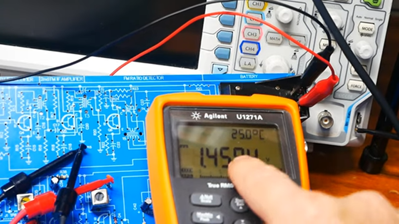
Using an Agilent meter on an Elenco kit,
is like…
using a WWV time standard to measure a junior high 100 meter dash.
using an Air Force $800 hammer to build a dog house.
using an Iron Chef to make an after school snack.
using Simon Cowell to judge kindergarten Show and Tell.
having Shakespeare write a Hackaday comment.
Methinks Ren protesteth too much :)
Sorry, just had to say it. Slow pitch over the plate ! My best to you and have a great day.
Hmm, a scathing Cowell type judgement using a Shakespeare quote. Well played.
Use the meter you have on the project you have in front of you. I’m not seeing a problem here other than your misguided flex or some feeble attempt at gate-keeping your favorite meter. What a pointless comment on a site that encourages learning.
Humor impaired much?
I had to stop watching when the video got to finding the current source for D4. The circuit drawing (and therefore the circuit board, since the schematic is drawn ON the board) is so poorly done, that without some previous experience with bad schematics, one might think that the current is coming from a previous stage. It may have taken an extra trace or two, and possibly a SLIGHTLY larger PCB, but the resistors and capacitors being used to supply and decouple various portions of the circuit should have been placed close to the circuits themselves. It’s not enough to put the schematic on the silkscreen, if this does not clarify how the circuit works.
Sorry, but I’ve spent way too much time as an electronics technician and then engineer, following signals across multiple pages of schematics just to see where the current came from, to accept this sort of practice as “educational”.
Wrong. Do it again.
If you have to do it as a professional engineer, then maybe it’s a good idea to make them suffer from the beginning.
We wouldn’t want them to go into the field spoiled, now would we? 🤣