An LM386 Oscillator Thanks To Tungsten Under Glass

Once ubiquitous, the incandescent light bulb has become something of a lucerna non grata lately. Banned from home lighting, long gone from flashlights, and laughed out of existence by automotive engineers, you have to go a long way these days to find something that still uses a tungsten filament.

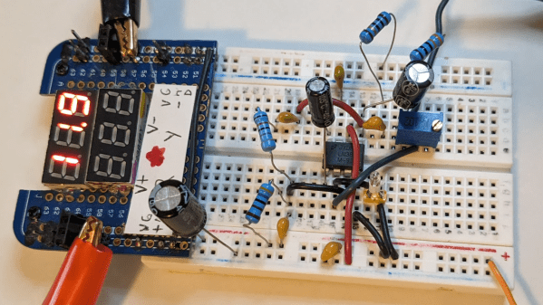
Strangely enough, this lamp-stabilized LM386 Wien bridge oscillator is one place where an incandescent bulb makes an appearance. The Wien bridge itself goes back to the 1890s when it was developed for impedance measurements, and its use in the feedback circuits of vacuum tube oscillators dates back to the 1930s. The incandescent bulb is used in the negative feedback path as an automatic gain control; the tungsten filament’s initial low resistance makes for high gain to kick off oscillation, after which it heats up and lowers the resistance to stabilize the oscillation.

For [Grug Huler], this was one of those “just for funsies” projects stemming from a data sheet example circuit showing a bulb-stabilized LM386 audio oscillator. He actually found it difficult to source the specified lamp — there’s that anti-tungsten bias again — but still managed to cobble together a working audio oscillator. The first pass actually came in pretty close to spec — 1.18 kHz compared to the predicted 1.07 kHz — and the scope showed a very nice-looking sine wave. We were honestly a bit surprised that the FFT analysis showed as many harmonics as it did, but all things considered, the oscillator performed pretty well, especially after a little more tweaking. And no, the light bulb never actually lights up.

Thanks to [Grug] for going down this particular rabbit hole and sharing what he learned. We love builds like this that unearth seemingly obsolete circuits and bring them back to life with modern components. OK, calling the LM386 a modern component might be stretching things a bit, but it is [Elliot]’s favorite chip for a reason.

Continue reading “An LM386 Oscillator Thanks To Tungsten Under Glass”

Active Signal Tracer Probe Has AGC

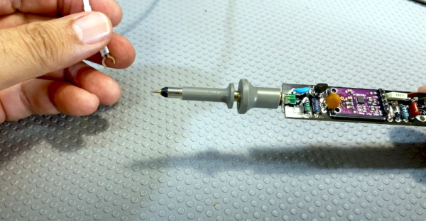
[Electronics Old and New] has a new version of one of his old projects. The original project was an active probe. He took what he learned building that probe and put it into a new probe design. He also added automatic gain control or AGC. You can see a video explanation of the design below. The probe is essentially a high-impedance input using a JFET that can amplify audio or demodulated RF signals, which is a handy device to have when troubleshooting radios.

The audio amplifier is a simple LM386 circuit. The real work is in the input stage and the new AGC circuit. Honestly, we’ve used the amplifier by itself for a similar function, although the raw input impedance of the chip is only about 50K and is less in many circuits that use a pot on the input. Having a JFET buffer and an RF demodulating diode is certainly handy. You’d think the AGC block would be in the audio stage. However, the design uses it ahead of the detector which is great as long as the amplifier can handle the RF frequency you are interested in. In this case, we think he’s mostly working on old tube AM radios, so the max signal is probably in the neighborhood of 1 MHz.

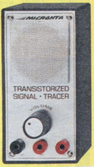
A similar device was a Radio Shack staple for many years

The module is made to amplify an electret microphone using a MAX9814 which has AGC. The module had a microphone that came off for this project. The datasheet doesn’t mention an upper frequency limit, but a similar Maxim part mentions its gain is greater than 5 at 600 kHz, so for the kind of signals this is probably used for, it should work well. We wondered if you could use the module and dispense with the JFET input. The chip probably has a pretty high input impedance, but the datasheet doesn’t give a great indication.

For years we used a signal tracer from Radio Shack which — if we could still find it — now has an LM386 inside of it after the original electronics failed decades ago. In those days, fixing an AM radio involved either using a device like this to find where you did and didn’t have a signal or injecting signals at different points in the radio. Two sides of the same coin. For example, if you could hear a signal at the volume control — that indicated the RF stages were good and you had a problem on the audio side. Conversely, if you injected a signal at the volume control, not hearing would mean the same thing. Once you knew if the problem was in the RF or AF side, you’d split that part roughly in half and repeat the operation until you were down to one bad stage. Of course, you could use signal generators and scopes, but in those days you weren’t as likely to have those.

Heathkit, of course, had their own version. It even had on of those amazing magic eye tubes.

Continue reading “Active Signal Tracer Probe Has AGC”

Educational Radio, Educates

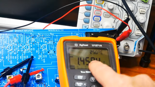
Analyzing and troubleshooting a modern AM/FM radio, digital radio, or TV can be a pretty daunting task. However, a common AM radio is easy to understand, experiment with, and repair. Learning about that will help you understand more complex circuits later. That’s the idea behind the Elenco AM radio which is built on a wide-open PCB with markings for all the important sections. [The Offset Volt] uses one of these to explain how a receiver works, especially how a diode detects the signal and how the automatic gain control works.

Between a series of diagrams and live scope demonstrations, you can see the effects of capacitance in the receiver along with other circuit effects.

Continue reading “Educational Radio, Educates”