All the hardcore geeks have alarm clocks where the bell striker is a hard disk read head… or at least they’ll be building them after seeing this. [Senile Data Systems] created an industrial voltage alarm clock out of decade counters that looks like it was unearthed from a fallout shelter (machine translation).
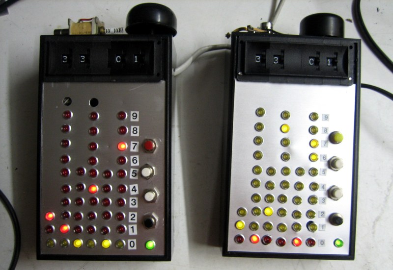
 At first glace you might mistake this for a binary clock since it uses a column of LEDs to indicate each digit of 24-hour time. It’s not, as each row corresponds to a pin on the CD4017 decade counters that make up the timekeeping circuit inside.
Thumbscrew wheel switches at the top of the bulky handheld unit are how the alarm time is set, triggering a bell along the top edge. The clock is driven by the 50 Hz line voltage and [SDS] tried using that AC to drive a solenoid as the striker on the prototype unit but it performed poorly. The use of a hard disk read head turns out to be the perfect striker, as heard in the video after the break. As for triggering from the decade counters, here’s what [SDS] told us about the design:
The switches’ outputs gets ANDed with a 10 Hz signal (on a 60 Hz grid it will become 12 Hz). This drives a slightly beefy transistor which in turn drives an electromagnet to hammer a bell which broke off my bicycle. Yes. This is a digital analog alarm clock. The clock portion is digital but the bell is analog and sounds like Grampa’s old wind up alarm clock.
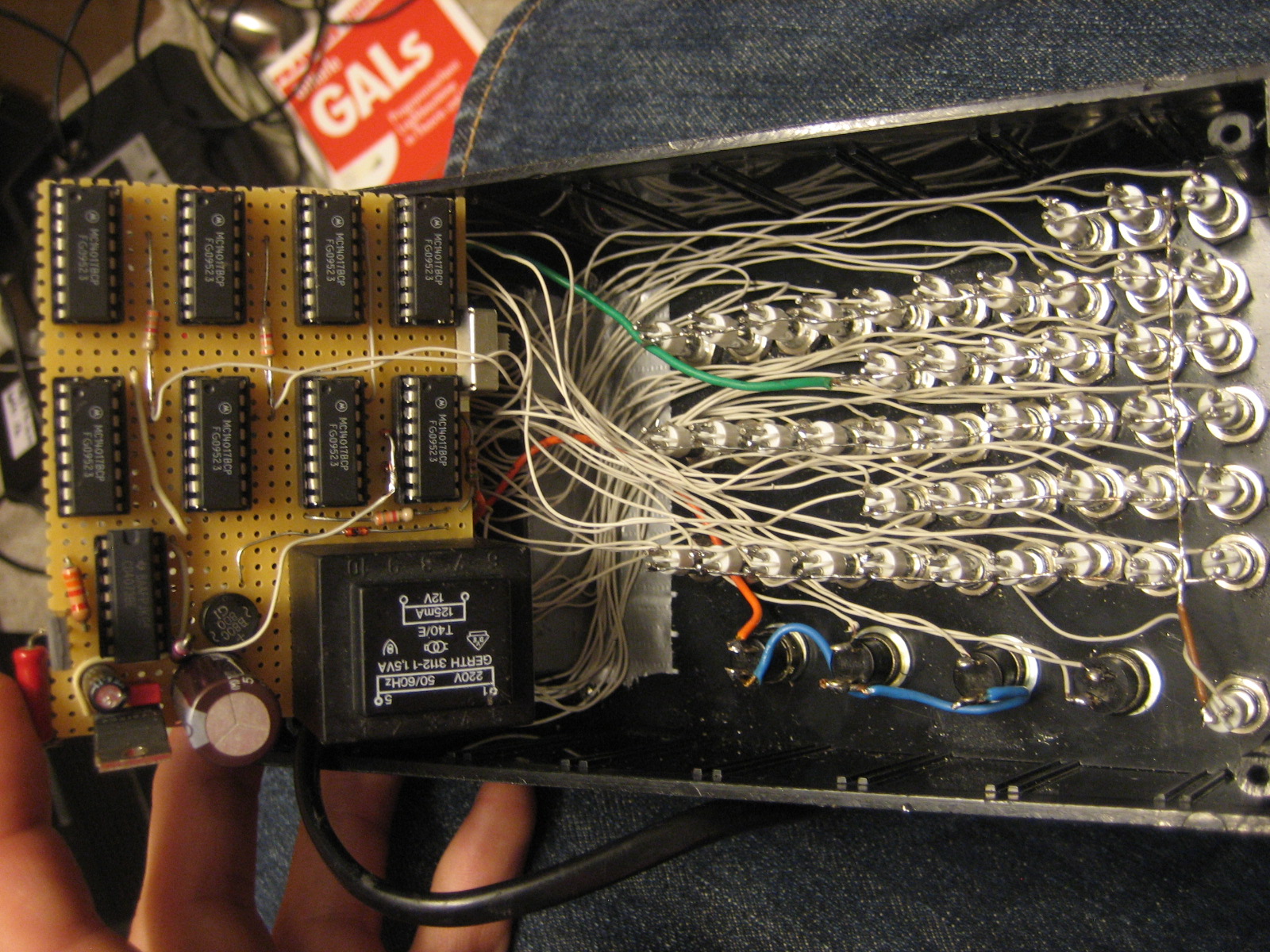
The build came about when a cache of over 600 industrial LEDs (24 V – 48 V) fell into his lap. This makes the insides of the clock something to behold as point-to-point soldering connects the panel mount lights and all nine logic chips. Add in that transformer for getting the line voltage and we imagine this thing has quite a bit of heft to it.
If you’ve ever had an alarm with a wind-up bell you know there’s no better way to jolt yourself out of a peaceful slumber and into the chaos of the real world. If the gentle tinkle of the hard drive head isn’t enough for you, this fire bell alarm clock will certainly do the trick.


Thumbwheel, not thumbscrew switches. Much less painfull way to set the clock.
Thumbwheel switches, not thumb screw switches – a much less painful way to set the time
Ouch, right you are!
If you didn’t have the thumb wheel switches, could probably use thumbscrew ones in a pinch
…And I thought that you did that to be funny. :)
Nice, but I’m a bit disappointed. The wires should be laced in nice, tight bundles running along the columns of LEDs, like in most of industrial electronic devices from 1960s.
And I say bundling wires is a wrong headed farce of an engineering decision. The current carrying capacity drops by a third, vs free air and should there be a single short, maybe half the harness gets involved because suddenly, red hot cheesewire slicing through everything and welding it all together. I also say reasons like vibration resistance are a wash, because then you get the shortest, tightest connection trying to resist the momentum of the whole bunch, rather than just a single wire, yeah, that’s gonna be more reliable than each connection for itself with a single wire’s mass to restrain.
Its LEDs…. current carrying capacity is practically irrelevant and already resistor limited.
These LEDs are said to run on 24–48 V, which I assume means they have built-in resistors, which probably means no resistors on the board driving them. If there’s a short circuit in the wiring, those resistors in the LEDs will be in the wrong place to help.
You’re correct on that.
The CD4017 however has internal current limiting built-in.
(which btw. just so happens to be the exact current needed to burn the fuses on some ancient OTP PROMs, which made them handy for programming those)
Ooh, with that string technique they used to use. What was the crusty stuff they painted on it to hold it in place, varnish?
I was too lazy for that and didn’t think of it. I wasn’t after a 1960s look, just something to get rid of some LEDs and CD4017s. And it’s the first time I built something that a Normal Person (TM) would not find totally useless.
I’d prefer to have used color coded wire, but I didn’t have enough and/or was too lazy to look for it.
Excellent build! It reminds me of the fat bodied bubble-LED “pocket” calculators of the 1970’s.
Is that a CRM 114?
I take a shortcut and have Codsworth wake me.
There’s something oddly pleasing about the aesthetic, like an old TI calculator, but with lights and switches having traded places. Quirky and functional. Noice
I tried to calculate the probability I will be allowed on an airplane with this thing. It came out 0.000131247%.
That seems optimistic, especially if you’re trying to go through the airport in Boston. They once arrested a woman for having LEDs on her t-shirt.
“Breathtaking”? Really?? The nomenclature isn’t even straight. This is Messy.
Agreed.
It looks like a rat’s nest from the insides and from the outsides you can clearly see that I can’t drill straight and also I can’t count (fixed that on the second clock though).
Fun fact: Except for the LEDs, there is nothing (physically) fixed inside both clocks. As soon as the bottom screws are tightened down, the pressure of all this junk – together with there not being much space inside – holds everything together nicely with the only thing that remains rattling being the bell striker.
Masking tape, ametal ruler, fine felt pen and an automatic center punch, applied roughly in that order will have your lines nice and straight.
Or just design the panel in your favourite CAD/drafting application, print it out, stick it doen and use it as a template for your center punch.
I am not in into bondage of wires but the drunken wandering of the rows and columns drilled without a nail-punch start of them in line isn’t worth the time and parts. Cover with masking tape mark out a grid and if it’s aluminum just press and make holes with a pointy tool.
Would you believe I did that? Both of that? And I was sober all the time? I suck at drilling and nail-punching – maybe I should have used a nail instead of the kerning (right word?) tool. But I don’t suck at soldering. And apparently not at engineering either. But I really rock at fixing electronic stuff. Which might come in handy when these clocks age…
Klasse gemacht, finde ich! 😎👍
Eine gedruckte Schaltung kann jeder machen, aber nicht jeder hat die Geduld für komplexe Handverdrahtung.
(Eng: Well done, I think. Everyone can use a PCB, but a complex, handmade wiring takes an amount of patience not everyone has got.)