If you’re serious about engineering the things you build, you need to know the limits of the materials you’re working with. One important way to characterize materials is to test the tensile strength — how much force it takes to pull a sample to the breaking point. Thankfully, with the right hardware, this is easy to measure and [CrazyBlackStone] has built a rig to do just that.
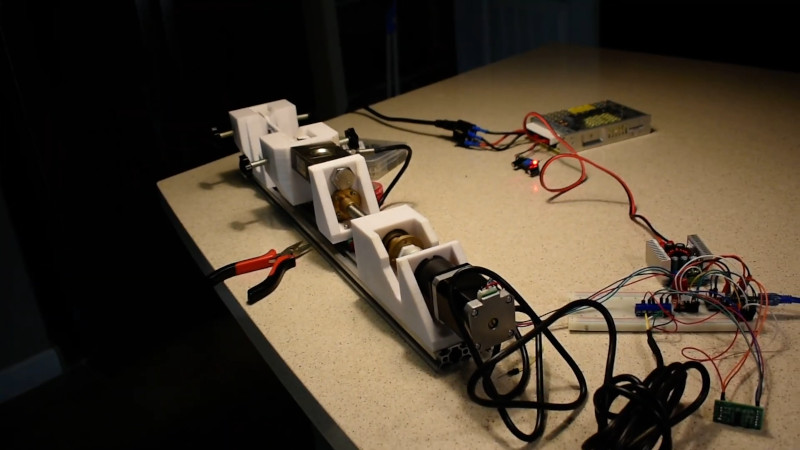
Built on a frame of aluminium extrusion, a set of 3D printed parts to hold everything in place. To apply the load, a stepper motor is used to slowly turn a leadscrew, pulling on the article under test. Tensile forces are measured with a load cell hooked up to an Arduino, which reports the data back to a PC over its USB serial connection.

It’s a straightforward way to build your first tensile tester, and would be perfect for testing 3D printed parts for strength. The STEP files (13.4 MB direct download) for this project are available, but [CrazyBlackStone] recommends waiting for version two which will be published this fall on Thingiverse although we didn’t find a link to that user profile.
Now we’ll be able to measure tensile strength, but the stiffness of parts is also important. You might consider building a rig to test that as well. Video after the break.


wouldn’t the 3d parts be flexing too much to get an accurate reading?
Make and test a number of parts and check the variance, statistical analysis is your friend.
And add multiple testing for different room temperatures.
And re-calibrate with extra measurements now and then.
And consider material fatigue.
And …
Mmmmm … lots of exciting mathematical fun but not very practical …
The metal testing machines flex too. You cal it out, as long as it’s repeatable.
I suppose that if the test setup is done accurately and controlled well, you will be able to extract meaningful data and detect critical material behaviour properties. The material will undergo plastic deformation prior to fracturing. By performing repeatable runs and analysing the data thereof, you should be able to determine the fundamental behaviour of the material to highlight the elastic and plastic ranges of the material which is generally unique to a specific material and is extremely useful for determining potential applications of the material.
If you’re only measuring force, and not displacement, it doesn’t matter. The force is going to be the same regardless of any flexing (assuming it’s not flexing so much that you get some geometric non-linearities).
Yes, but if you aren’t measuring displacement the only thing you can measure is ultimate tensile strength (when the force suddenly drops to zero). UTS isn’t very useful for most plastics because by the time they reach it they’ve long since yielded (plastically deformed) and any parts made from it are likely comprehensively ‘broken’, even if they haven’t yet split into multiple pieces.
For any useful measurement of practical strength, you need to be looking at a stress-strain curve, which means you need to measure displacement.
If you want to measure displacement you can put a strain gauge on the test material itself, or an LVDT, dial indicator, etc. on the point that will have the most similar displacement to the test material. ie. the test material itself, the mount, etc.
CNC Kitchen on youtube has one also
There is a standard for the design of tensile test specimens, if you follow it then you can compare your results to others. While you are resting you also might want to do a Charpy V-notch test to check for brittleness.
“One of important way to characterize materials is to…”
That doesn’t matter if you’re just trying to measure ultimate tensile strength. The load cell will measure the applied force regardless of creep. As long as you can reliably detect the point of break then you should be ok.
Trying to measure elongation, strain or Young’s modulus would require predictable stiffness in the rig.
I giggle a little bit at this for personal reasons. i want this setup to have an open source sound bite of “remove instrument” once it gets to .02% offset, just don’t forget to add gauge marks so you can measure your elongation.
Who else read; “Testicle Testing Machine…”
Cartman? Is that you?
Would such a design benefit from the use of a thrust bearing?
Hi, I am the person who made this tensile testing machine (this is the original instructable https://www.instructables.com/id/FULLY-FUNCTIONAL-Tensile-Testing-Machine-Tinkercad/). Thanks to whoever put this on Hackaday!
I have a new version of this machine that I’m going to publish in early October which has improvements made based on the lessons I learned from this machine. Some of which include metal reinforcements to hopefully eliminate flex in the fixtures.
To answer some of your questions:
– Wouldn’t the 3D printed parts flex and cause inaccurate readings?
Yes, it’s inevitable that flex exists within 3D printed parts, however, the deflections were surprisingly little according to the Fusion 360 simulations. I doubt that my simulations were accurate though, and I only applied a total of 500N to the parts.
– Does this measure strain/displacement?
No, but you can probably use something like a video extensometer to measure the strain data. Though flex in the fixtures may make the results a bit inaccurate.
– Would this benefit from a thrust bearing?
I used a two row angular contact bearing for handling the axial loads. Thrust bearings would also work, but it’d be extra work to keep a preload on them.
– Have you tested the reliability of the results?
Yes, I am a high school student and am in the process publishing our results on finding the tensile fracture forces of testing specimens in Journal of Emerging Investigators. Right now it’s still not published though :/
– WHEN IS VERSION TWO COMING!?
I already bought the parts to make version 2, and I’m planning on releasing it in early October. But it might be delayed due to COVID shipping problems. I have the design files for version two and have considered releasing them right now, but I would rather make sure that version 2 works before I do so.
If you have any questions regarding this project, feel free to email me (zhangxieshi369@gmail.com) or reply to this comment.
Any idea what the testing rate is(i.e. mm/min)? This can affect strength in materials (aka strain sensitivity).
Sorry for the very late reply. The speed can be set using the arduino code, the maximum of which depends on the gear ratio of the stepper motor, your microstepping settings, and your lead screw pitch. I no longer remember what I have set my testing speed to, but the it can simply be changed to your desired value in the software.
(Also, the new version is here https://www.instructables.com/Universal-Tensile-Testing-Machine-VERSION-TWO/)