There’s an unexpected part of hacking that is very difficult to get right, namely photographing printed circuit boards. Everything seems to catch the light, making for a complex dance of manipulating light sources and camera angles. We were thus captured by [Roman Valls]’ budget rig for taking PCB photos that makes ingenious use of roadside trash to achieve a result.
It was inspired by a video featuring a much more accomplished rig, which he set out to emulate for much less outlay. Instead of an expensive lens, he’s using a Nikon camera with its kit lens. And instead of a tripod there’a a scrap drawer salvaged from the roadside and modified to become a camera holder. Lighting is diffused by baking paper, and the result is a rig that can photograph PCBs with neutral lighting and without annoying highlights.
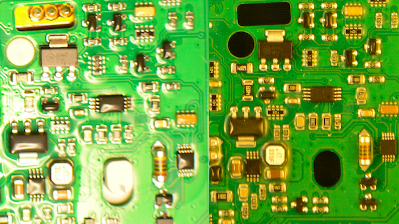
We especially like work that takes junk and makes something useful from it, and though our purpose isn’t in reverse engineering it’s impressive to see how well the technique reveals the traces. We’ll definitely be experimenting with some of the techniques herein, and those lighting tips might also work with the Hackaday ear camera microscope.


Once you have the photo, you can place the resulting images on a layout for reverse engineering quite easily in the open source PCB layout editor pcb-rnd
http://repo.hu/cgi-bin/pool.cgi?cmd=show&node=background_image
Does this allow working back towards a schematic?
You can export a netlist based on what is drawn. YMMV depending on your preferred schematic editor’s preferred netlist format and support for back annotation.
I use KiCAD, but I don’t recall it supporting back annotation.
Any recommendations for schematics editors for this application?
pcb-rnd lets you identify galvanically connected copper features you have drawn, and claim the connected features as a net in the netlist window. pcb-rnd can then export back annotation patches that would reflect the newly created nets.
These back annotation patches are supported in more recent versions of the schematic editor gschem. You would need to have a bare bones schematic in gschem with the necessary symbols that the back annotation patches would then be connecting.
There aren’t any other FLOSS options I am aware of that would allow this, but pcb-rnd developers could in theory implement different back annotation patch formats if there were demand for it, since netlist formats are not that complicated.
There isn’t a reply button on you last comment about back annotation, so I’m replying to this one instead:
Awesome, thanks for sharing! I will check out pcb-rnd, hope it is also as user friendly to learn as KiCAD.
Been there, done that!
https://github.com/Squonk42/TL-WR703N
A much better solution is to use a flatbed scanner, once you removed all the electronic components using a hot air station: this way, you get zero lens distorsion and up to 1200 dpi resolution with constant light.
I use a scanner too, if the components are not tall, it works fine with them on, just mask off the bare glass with a couple of sheets of A4.
And you will see the whole PCB, so better, unless you want to keep the device functional.
I use a polarized ringlight (that is, a ringlight with a polarizing filter on it) and a polarizing filter on the camera, set to the angle that blocks specular reflection. Before filters it’s a 9600 lumen light source (100 watts of high-CRI LEDs) to make up for the filter losses and get decent depth of field, but I normally dial it down to 1000 lumens for video.
It’s perfect lighting: no shadows, and you can’t see any reflections of the light source. Almost surreal.
Some oddities are that LCD contrast varies with their orientation, and clear plastics take on strain rainbows sometimes.
This is a very interesting approach for sure. Do you have any sources of hacker-friendly polarized ringlights? I see a lot of high-end commercial options for stereomicroscopes.
I have a cheapish USB microscope and a stand that came with it that I use for most of my circuit board inspections, but it has a low enough zoom to be useful for portions of a PCB.
Would be great to cobble together a polarizing solution with that.
My “Polaring” ringlight is scratch-built: 16 “5W” LEDs thermal-epoxied to 4 heatsinks on the ring. It handles flashes of 400W, 100W for a few minutes, or 25W forever (video mode).
The polarizers are cut from a single cell phone screen replacement film, cut to size and mounted on microscope slides – the film must go on the *object* side of the glass to work properly. Each of the 4 lights has an aperture dictated by that microscope slide: about 2×5 cm.
The whole thing, heatsinks and all, is a 3D-printed assembly (in ABS — PLA would melt), and mounts on the camera filter ring, and the (rotatable) camera polarizing filter mounts on that.
Brilliant! Thanks for sharing
Indeed, simple and superbly functional. Yet another idea I feel I should shamelessly rip off… when I get round to it.
Seen the same concept in use before for other uses. But never as a ring-light.. and that makes so much sense, if you build it yourself you also know (or at least can work out) the orientation which lets you do lots of other fun things.
There’s actually a great product/project out there already for RE of PCBs, I stumbled across it randomly on Instagram. Take a look at inspectar.com or their IG handle, inspectarteam. Fully automated extraction of schematics/pinouts, all you need to do is just drop in the chip # and SMD values!
Just downloaded and played with this. I can’t see anyway it could do automated net extraction without seeing internal layers. The sight doesn’t seem to mention that use case either.
What would be a killer application for this would be to run it on the host that’s connected to a trinocular boom microscope. I could easily look up to see the nets that need rework. Unfortunately it doesn’t support linux although I suppose with a suitable webcam connected over USB to a tablet I accomplish the same thing with the free version… Hmm, this might be a rabbit hole I have to chase down.
I have a boom magnifying glass for very small electronics pieces. I used 6 headlight ring lights – the ones that come in a circle, in successive smaller sizes arranged into a sort of tower on top of each other and on a thin wooden circle pallet with the glass magnifying lens in the center- it connects to a folding boom from a microphone, with the last ring being 80mm I believe – every 10mm in diameter – Hot glued together to stack. Each ring should fit into the side of the next ring’s LED mounts.
I then have those connected through a 12v 5 amp PWM controller (inexpensive). You could do that with diffused material to get a good indirect light with the camera in place of the lens. I needed something I could look through and get direct light onto parts. The hardest part was to source the glass lens that was large but not too heavy, I think I came up with a 4 inch hand magnifying lens in the end after buying like 5 of them of different quality on Amazon, beware plastic lenses and low magnification glass ones. You can also place another smaller magnifier on top of that lens for extra magnification.
They are called “LED Angel Eyes Halo Rings” – get in white only, they are roughly 60 SMD LEDs in a circle. If you want photos of the project: https://drive.google.com/drive/folders/1LHmVam2rW-37ktnpbiLh1Q-EUD0oi9uo?usp=sharing
I made a slip on ring light for my kit 18-55 lens (canon 1200d) out of a lighted mirror. Pop the glass out, slap a lipo cell and/barrel plug on it (havent figured out if and how I could pull power from the shoe yet), and cut a hole in the plastic housing to slide over and ‘clip’ around the lens tube. I also went so far as to spray the LED illuminated ring area white and the rest black. Its no pro ring flash, but definitely gets the job done!
So make a soft box. K, got it.
I use a black plastic tray table (for dark background), a tripod and cheap remote shutter for top down long exposures (to avoid high iso noise plus a 2sec delay to avoid shake from the remote wire and such), and a pair of 60weq gooseneck desk lamps setup for indirect/bounced light (usually off of some small white boards or a thick white grocery bag), sometimes a diy ring light I made from a lighted mirror if the reflection isnt an issue (though I do have some polarizer sheets laying around, might try that polarizer trick from an above comment). Using a longer exposure technique, while suspectable to jiggles, results in a nicely saturated clean crisp image. One thing I discovered (that no photography nerd talks about, except the chick whos YouTube i happened across…) that REALLY affects the image quality in a very subtle way (for non-photography nerds at least) is figuring out the best aperture/f-stop setting for your given lens/body. Especially if you cant calibrate the fine microfocus (like the canon 1200d doesn’t allow).
The biggest secret is take your time. The more time you allow for set up and capture the better the result will be … once you stumble through learning which settings to tweek….