It was with considerable interest last month that I set out to track down where in the world there are still factories making tubes. My research found them in Slovakia, Russia, and China, and it’s fairly certain I didn’t find all the manufacturers by any means. There appeared to be a whole class of mundane tubes still in production that weren’t to be found on their glossy websites. A glance at any outlet through which Chinese modules can be bought will find this type of tube in small audio amplifier projects, and some of them can be astoundingly cheap. When faced with cheap electronics of course I’m tempted to buy some, so I parted with about £10 ($12.50) and bought myself a kit for a two-tube device described as a stereo preamplifier and headphone amplifier.
An Unusual Tube Choice For Audio
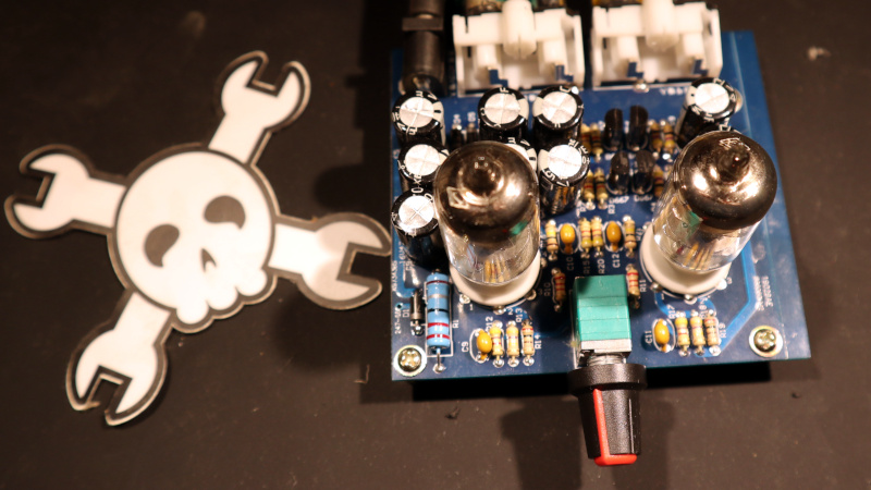
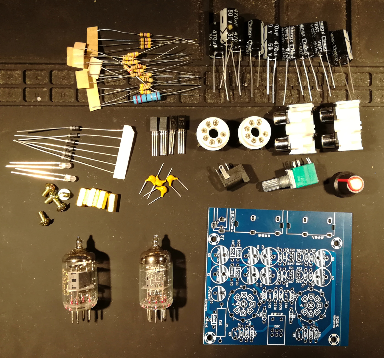
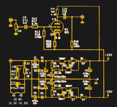 What I received for my tenner was a press-seal bag with a PCB and a pile of components, and not much else. No instructions, which would have been worrisome were the board not clearly marked with the value of each component. The circuit was on the vendor’s website and is so commonly used for these sort of kits that it can be found all over the web — a very conventional twin common-cathode amplifier using a pair of 6J1 miniature pentodes, and powered through a +25 V and -25 V supply derived from a 12 VAC input via a voltage multiplier and regulator circuit. It has a volume potentiometer, two sets of phono sockets for input and output, and the slightly naff addition of a blue LED beneath each tube socket to impart a blue glow. I think I’ll pass on that component.
The 6J1 seems to be ubiquitous throughout the Chinese kits, which is surprising when you understand that it’s not an audio tube at all. Instead it’s a small-signal VHF amplifier, a rough equivalent of the European EF95, and would be much more at home in an FM radio receiver or turret TV tuner from the 1950s. I can only assume that somewhere in China there’s a tube factory tooled up for radio tube production that is targeting this market, because another tube you will see in audio power amplifier kits is the FU32 or QQV03-20 in European parlance, a large power beam tetrode that might have been found in a 1950s military radio transmitter. Still just as if you were to use an RF transistor in an audio circuit it would give good account of itself, so it is with an RF tube. There is no reason a 6J1 won’t do an acceptable job in a circuit such as this one.
Other than in its slightly unusual power supply, there’s nothing at all remarkable about the preamplifier circuit. The 6J2 is wired as a triode, and because a common-cathode circuit is designed to drive a high impedance, it’s safe to assume this won’t be a very good headphone amplifier. It’s a simple preamp circuit that has graced the small-signal end of countless tube amplifiers, including my youthful folly.
Building the kit was as straightforward as any other through-hole design, and made for an enjoyable half-hour or so. There are no special things to note, I simply worked my way through it, first resistors, then diodes (but not those LEDs), transistors, capacitors and finally larger parts such as the potentiometer and sockets. A visual look over showed nothing of concern, so I plugged in the tubes and applied 12 VAC.
It’s amusing, this must be the first time I’ve ever used a new tube socket rather than one scavenged from old equipment, so I was unprepared for how stiff it was to plug in compared to one with years of heat cycles to soften its metal. On turning the kit on I was rewarded with a soft glow from the tube heaters, and measuring the voltages I found that it was generating about plus and minus 30 volts. A quick check applying some audio to it showed that it was indeed amplifying audio and it didn’t sound bad, but I needed a little more than that. It’s time to characterize the amplifier, is it any good?
Way Too Much Instrumentation For A Ten Quid Amplifier
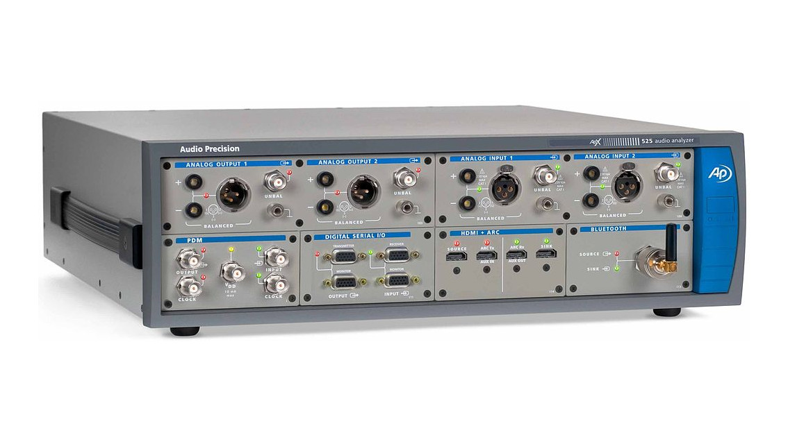
How do you characterize an amplifier, or any other piece of audio gear, for that matter? There are four metrics worth knowing: the gain, frequency response, phase response, and harmonic distortion. Frequency response relates to the range of frequencies it accepts, phase response relates to the phase shift between output and input at any given frequency, and harmonic distortion is usually expressed as a percentage of the output spectrum that is due to the non-linearities of the amplifier rather than having been present at the input. There are specialized instruments referred to as audio analyzers that will automate all these measurements by injecting a very high-purity sine wave into the device under test and measuring its output, but they are extremely costly and beyond the budget of a Hackaday scribe.
For this amplifier the frequency and phase responses are not likely to be concerning, so I would have to find a way to measure its distortion. Fortunately I was able to borrow a Keithley 2015 precision multimeter from a hackerspace friend, this very high quality instrument unexpectedly has a THD (Total Harmonic Distortion) function and its associated signal generator built-in. I suspect it may be aimed at the comms industry rather than the audio business, but it gives me what I need and I am very grateful to my friend. Set up alongside my trusty Rigol 1054z, I was ready to characterize the board.
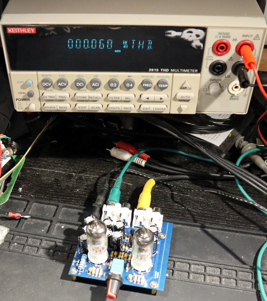
I set up the generator at the ubiquitous audio testing frequency of 1 kHz, with a 100 mV pk-pk sine wave as input to simulate a lower-level audio source. The output at maximum volume was 4.85 V pk-pk, at which the THD was 1.31%. I calculate that as 37.31 dB. Adjusting the volume for unity gain, i.e. 100 mV pk-pk output, gave me a 0.03% THD reading. Giving it a 1V pk-pk input to simulate a line-level input gave me a significant level of visible clipping and an astronomical 32% THD at maximum gain.
What do these figures tell me? At low signal input levels it has the potential for a low THD, but even then it’s not into the three-digits-past-zero zone you’d expect to see in a high-end audio product. At higher levels it starts to degrade significantly, but given that it’s a preamplifier rather than a line-level amplifier that should be hardly surprising. It’s possible that some negative feedback would tame it, however I’d then be worried that its phase response might suffer.
The question is, does it matter that it’s not a super-high-end preamplifier? For ten quid spent, not really. If you keep the volume low enough and hook it up to your hi-fi it’ll sound decent enough, indeed that’s just what I did. And it sounds, well, like my hi-fi system. No special “warm valve sound”, but it did give me the momentary cachet of a pair of glass tubes on top of the stack.
Have I Bought A Masterpiece, Or A Toy?
There is one final thought with respect to this amplifier, and it returns to what I said earlier about its being described as a headphone amplifier by the vendor. A single-ended tube amplifier has a very high impedance output, which is to say it’s good at delivering voltage, but not current. Something with an impedance in the tens of kilo-ohms is fine for it to drive, but not a typical pair of headphones with an impedance in the tens of ohms. I didn’t even try, because I know that it wouldn’t do a very good job. All is not lost however, because it’s possible to make a simple headphone amp with this circuit if you’re prepared to add to it a little. Back in the day it might have had a step-down transformer on its output, but those are hard to find in 2020, so an alternative might be to use a MOSFET source follower as a buffer. It’s one of those projects that I might find myself returning to with this amplifier.
There’s a lot of talk among a certain section of the audio enthusiast community about something special surrounding a tube amplifier. Pseudo-technical explanations involving distortion in even harmonics are trotted out, and a lot of fancy tube hi-fi kit is fawned over. It’s true, that a good tube amplifier can be a very good amplifier indeed, but after having been right through this subject over decades I have my doubts over whether the mere presence of a tube confers anything extra-special.
I think it has its roots in the first generations of transistorized amplifiers in the 1960s and 1970s, when germanium transistors and single-ended power supplies requiring hefty electrolytic capacitors on the output delivered some models with not-very-good performance, but we’ve moved on since then. Superlative quality transistor amplifiers were a done deal decades ago, and while their tube siblings stand alongside them in quality, I think it’s dubious to claim too much else beyond saying that in audio as everywhere else: you get what you pay for. Buy one of these little kits and have fun playing with a tube circuit for pocket money prices, but don’t expect too much from it.


Nice article. The amplifier has some negative feedback from the un bypassed cathode resistor and the really nice low level linearity you are seeing is probably just the center of the transfer curve.
I’ve always harbored the suspicion that the’tube sound” had as much to do with the characteristics of the output transformer as anything else and not strictly the tube. (Impedance match with the tubes, core nonlinearity, saturation, etc.) Just a thought.
The Iron is the heart and soul of the amplifier.
I’ll 2nd that suspicion about the transformers. Drive a core into saturation and you get some nice nonlinearity, not entirely unlike the soft-limiting from the tubes that is so often cited as the cause for the desired kind of harmonic distortion.
was experimenting with this amp 10 years ago and dumped it as 6j1 sounds really poor compared to 12A×× tubes which are available from Chinese maker with exact size
It sounds like this fun toy might be better suited to amplifying guitars, where all that distortion would be better appreciated.
Not measured, but always a problem with tube circuits, is noise. A properly designed transistor and/or audio IC circuit would be quieter, more efficient, smaller, lower distortion, and have higher output voltage capability and lower output impedance. It would last longer. Probably have less crosstalk, too.
Nonetheless, it’s a fun little project and nice to see here.
But apart from that, what have transistors ever done for us?
Hi! Ever tried a Nuvistor? Or a an ECC91/ECC92? 😉
Yep. Very small tubes. In very low noise front end on a good FM tuner of the 60’s
The end of the article reminds me of something my old buddy used to say.
If he wanted to make a lot of money doing very little work, he would sell high end audio equipment. Not the good kind mind you. No he would target the “audiophiles” who buy solid 24k gold headphone jacks and $500 tubes because it “sounds better”. It doesn’t matter that we can use math to show that no it’s just a lot of excess noise and garbage the tube is not helping make anything better just slap the random filter on any synth and you’ll get a similar result. The “audiophiles” will lap that shit up because you put a high price tag next to it.
So yeah why do those premium tubes sell. Because fools with money are easily parted.
This makes me wonder:
Did people like this ever bother to do a proper research or do any serious testing before making such claims? You know, using a oscilloscope, do measurements etc..
I don’t mean to judge, but from my experience, primitive hardware doesn’t necessary lead to bad results. For example, a real detector crystal has a better sensitivity, linearity etc than the average diode (both Silicon and Germanium). You can check this on YT. Several videos by oldtimer confirm this. And they show you their scope in action, instead of just making claims. 🙂
Can’t speak for the commenter, but for myself as the author with respect to hi-fi audio: yes. Over 30 years of it, some professionally, some for myself. I’m not an ultimate guru on the subject, but I like to think I know enough about it to comment.
As to tube Hi-Fi? Yes, it can sound amazing. It’s awesome levels of cool too, but it’s not automatically better than solid state electronics of similar quality.
Agreed. Some FET circuits, for example, are very good.
Thank you very much for your reply. 😎
A basic crystal set (with cat’s whisker) was a rite of passage for any kid with radio electronics inclination. With just passive components: antenna and ground, coil, detector, basic headphones where could the distortion come from? :-) It did sound fine.
I actually have built and then ran this very same model through testing using a signal generator and an oscilloscope, and I was actually surprised how clean the signal remained when not pushed extremely hard. I do remember this device being particularly sensitive as the potentiometer made a huge impact on the voltage amplification as evident from the scope. I don’t recall if the pot was linear or log, but it felt more linear, albeit with a very large delta with minimal movement. I also threw in a good pair of matched tubes instead of relying on the included tubes. I probably should have taken measurements with both and theoretically still could as this was an easy setup to test, but do recall the sound being quite similar regardless of the tube selection, something that I found quite interesting.
IMHO, this is a fairly simple setup in theory and the included components don’t suck either, and you are correct in saying that [for the most part] “primitive hardware doesn’t necessarily lead to bad results.” I’ve discovered it’s all in the circuit design and with older analog devices, a basic common sense design is usually the most effective route. That’s why I really enjoy analog devices in the chain, but knowing how to best control them does help a ton. For example, keeping a basic three band EQ in the chain helps best when modeling the sound by cutting instead of boosting signal. Boosting will also result in distortion because it’s still amplification, just only to a set band. There’s a handful of rules like this that I go by, but simple hardware (preferably the kind that’s easily modded) is almost vital. I’ve also seen larger, more commercial devices playing by the same rules as when you open them up, you will gladly discover a very modular design centering around, at times, dozens of areas that perform specific tasks. Everything in that case will almost always “play nice” in the grand scheme of things.
I’m not even sure what you’re trying to get at, that tubes themselves are bad? Are we supposed to be buying cheap tubes or not buying tubes at all? Can you tell me if it’s OK to own a $300 guitar tube amp? Is it OK to own a cheap tube preamp, or should I get a DSP or “the random filter on any synth”? Eagerly awaiting your response, I need to know how to enjoy my musical equipment.
I see it as a comment on the customers, not the components.
Here’s another headphones amp based around an EF95..:
http://www.elexs.de/ef954.htm
By the way, the EF98 was used in car radios and later revisions of the Kosmos Radiomann/Radio gnome construction kit (early kits used ancient DM 300)..
The sister tube, EF97 also works with 12v (6v heating).
I just built the same kit last weekend — the first valve circuit I ever used. Haven’t measured distortion or BW yet.
While it is in all the schematics, I think the R16 from the output to -28 V should really be to GND, else you’ll get a huge click (bang ?) when you plug in headphones (jack is between output and GND).
Correct. Or connect shield of headphone to-28 rail. It is a design mistake.
The schematic is incorrect. I can see from the PCB traces that R16 does bias to ground as it should.
Have to say, that’s just the one from the supplier’s website.
I think that if tube sound is “special” (and I’m not saying it isn’t) then it MUST DISTORT!
Sure, it’s SPECIAL DISTORTION but if it didn’t, then it would be just another soul-less perfect amplifier.
But the other perceived attributes of warmth and harmonious-ness really have nothing to do with tube characteristics, but they do make sense with transformers if you consider dynamic bandwidth changes and second order non linearity core saturation characteristics.
I’d love to see a comparison of a fender twin transformer driven in class AB1 by some high voltage FETs.
I’ll bet it would sound like a fender twin.
Personally, I would like a “soulless”, as you put it, perfect amplifier but they are too expensive.
I am reminded of a story about art galleries and museums, they would happily have an old painting cleaned to the state it was when it was when new, but then insisted on the cleaned painting being covered over with a layer of brown varnish to make it look “authentic”.
That perfect amp would be great for “finished” music at home. All sound “changes” are already in the source.
Not so great as a guitar/harmonica/other instrument amplifier.
Are we not far from repurposing as a DDS VFO that can drive a tube transmitter? 4.8V p-p output, add some filtering, hmmm…
Done already. There are DDS VFO designs out there for driving the likes of vintage Heathkit, Eico, etc. “Novice” transceivers. I seem to remember the ideal “Vintage” DDS VFO’s output was designed to plug into the glow set’s crystal socket.
Novices were ‘crystal bound’ to minimize the chances of havoc with frequency control and out of band operation. There was no age limit, there were 7 yr old novice class operators. VFO’s were ‘off limits’, and having a VFO plugged in the crystal socket sounds hilarious. :-)
One of the things rarely mentioned is the power supply. In old equipment, there was no voltage regulator, so anode voltage would drop with large signals. This obviously influences sound.
I think that the power supply sag (especially with higher resistance tube rectifiers) is a lot more complicated than it looks in that screen voltage (which also sags) determines output tube gain as well, and voltage and current determine drive impedance to the output transformer, so my suspicion is that there is a fairly complex dynamic compression going on in guitar amplifiers that might be easily overlooked. (at high output)
Just gotta squish the tops and bottoms of those sine waves somehow. (Or, just the tops, if you’re a discarded Deacy resurrected by an astrophysicist)
Transformers have somehow avoided notice for decades. They’re heavy, so even before they were eliminated, manufacturers were trying to smallen them, and it was not uncommon to put slightly under sized ones into designs. Less iron pushed at same power level will get closer to saturation.
I too suspect this is where 90%+ of the magic sound of tube amps really comes from.
Good quality tube electronics back in the day would often have a huge LC pi-network filter on the output of the rectifier, with a pair of big electrolytics and an inductor of similar size to a mains transformer. The idea was that this circuit would help with this.
Only helps with hum. BTW they would use a saturable core inductor for the choke which would change reactance based on DC current flow. Voltage regulation is a result of the impedance of the power transformer including its effective source resistance, rectifier resistance (more prevalent in tube rectifiers like a 5U4 with significant plate resistance), filter choke impedance and effective resistance. With additional load, the power supply voltage will sag based on the sums of effective source resistances and the voltage drops thereof. Without a swinging choke, the AC ripple also changes with load. Proper selection of the choke reduces this ripple variation.
Are you discussing capacitor input or choke input smoothing circuits or both. Either way a big beefy power supply will always beat an “ecoomically optimised” one.
Pi network like Jenny described with 2 caps and a coil.
In high voltage applications, or if you want to use lower voltage rating parts, the choke can be between the negative side of the capacitors with the last capacitor negative terminal being the connection to ground.
Totally agreed but beefy isn’t the rule. Proper passive power supply design is a whole lot harder than it looks and requires dynamic load analysis before you can even start.
If you have a constant load, most design problems disappear.
By the way, it’s a lost art.
Hey if you had fun making it and the tube amp works, I think that’s great. :-)
Exactly!
Why does the schematic have only one valve and the PCB two?
Is the second valve wired in the same way and left to the imagination?
In the Q&A section of one of the vendors someone seems to think only one tube is functioning, but looking at the PCB traces this does not seem to be true.
(Sorry for asking, I’m a beginner at this)
Stereo.
Yes, I get that, but why does the schematic not reflect that?
It’s likely the same schematic for each channel, so rather than have a redundant double schematic, they chose to only draw one.
It’s a stereo amp, the diagram is for a single mono side,
So the diagram does not match the PCB. Thanks.
Slovakia must be “thrilled” by the fact it found itself among China and Russia :D
Plenty of misinformation here, especially regarding valve usage.
So please, feel free to enlighten us. Your post is quite hollow with just that statement and nothing to back it up.
@Jenny List said: “How do you characterize an amplifier, or any other piece of audio gear, for that matter? There are four metrics worth knowing: the gain, frequency response, phase response, and harmonic distortion.”
To be thorough, there is another key parameter of interest: Group Delay. Phase response is the phase delay at various frequency points. Group delay response is the rate of change (first derivative) of the phase delay at various frequency points. Phase response and group delay response are not the same thing have different effects depending on the complexity of the waveforms passing through a system. If your system is has a linear phase response then phase response and group delay are the same. But that’s never the case in the real world. Group delay will give you insight about how the parts of a complex (e.g. modulated) waveform propagate through a system at various frequencies. In music for example, consider a flute playing a single note. Let’s assume the flute is producing a near perfect continuous sine wave at a single frequency. In this case the group delay and phase delay characteristics will have little affect on the flute sound. On the other hand, consider a muted trumpet playing a short staccato note. The trumpet sound will be distorted and spread throughout time and frequency, as if it is modulated by other frequencies. This is where both the phase response and the group delay response come into play, and with complex modulated waveforms like the trumpet note example, group delay response can be dominant compared with phase response. Think of group delay response as causing the dominant tone in the trumpet waveform to propagate at a different rate than the modulation parts of the waveform that make up the complex trumpet note waveform. The effect is a “spreading out” of the original waveform. In digital communications where you might use modulated analog sine waves to represent different logic levels, group delay is very important. Without good group delay response these coherent in time modulated signals will interfere with each other, a conditional formally known as ISI or inter-symbol-interference. In a system like a telephone line that is carrying modulated digital signals between analog modems, it is not unusual to provision the telephone connections through pieces of equipment known as group delay equalizers (GDEs). Once group delay equalized, a circuit will provide a lower bit error rate for a given signal to noise level (i.e. bit energy to noise density ratio) primarily due to lower ISI.
For a preamp, the most important thing after the gain (for me) is signal to noise ratio (or Noise Figure).
It seems to be an audiophile ‘thing’ to not publish figures for this metric either.
Hi there !
I really enjoyed the article. Congratulations !
I do have a question, if you don’t mind: I bought a pre-amp like this one, already build, with a pair of 6j1 valves. It was sold with a 12V power supply, supposedly, rated at 1A. The parcel arrived later on with a weaker 12V power supply rated at 500mA. Is there any problem running it at 500mA instead of 1A ? Any real difference ? Is 500mA enough for this device ?
Thank you
An amp “modulates” the power you feed it with the power supply. Feed it less power, you’ll get less amplification. Since it is class A at least it won’t run as hot.
Got it. Thanks for the reply !
I wrote my postgraduate thesis on a comparison between triode and solid-state amplification. It wasn’t so much about a complete amplifier, but about the raw characteristics of the amplifying component and which are different and how.
And there’s a lot above that’s worrying, people claiming it must be transformers only, or it’s noise, and so on.
The fact is, whether you like it or not, a vacuum tube has a different output to a transistor, and sure all those other things apply as well, but signal changes STACK. So, of course a transistor is acting as a nice big signal changer, but so is each triode pre-amp stage.
And the difference is quite striking. The normalised gain ratio on 12AU7/12U7 vacuum tubes is a 0.8:1 slope, on transistors it’s 1:1, the vacuum tube has a completely different dynamic range because of that; you have a roll off at about 30KHz WITHOUT extra biasing/filter caps, the transistor was completely flat; you have the compression/distortion on a vacuum tube which is a slow rounded clip, resulting in harmonics across a larger frequency range; when you drive it REALLY hard a transistor will start to rectify and invert the output, the vacuum tube just stayed a rounded sine-ish wave.
And so on.
Now, the tube in this is different, and because it’s a radio tube it may react differently to frequencies, but I bet it shares at least some of these things in common, and I bet you anything that it is possible to point to a single component in an amplifier and go “all the good sound stuff comes from this bit”, because it’s a whole signal path.
it’s the companding effects of valves that make the ‘nice’ sound
i’m playing with a k272a amp kit i built nearly 10 years ago, comparing it to (amd feeding it from) the headphone output of my samsung monitor’s DAC – and what i can gather from it, the valves are performing a compander effect with the audio – snappy highs are subdued, mids are pronounced and the bass is emphasized- it’s a different sound from the direct feed and not able to go as loud as the direct feed. its nice, like the over saturation of a good type 1 cassette but it’s not ‘BETTER’ its just different