It’s been a while since the last installment in our Know Audio series, in which we investigated distortion as it applies to Hi-Fi audio. Now it’s time to return with part two of our look at distortion, and attempt some real-world distortion measurements on the bench.
Last time, we examined distortion from a theoretical perspective, as the introduction of unwanted harmonics as a result of non-linearities in the signal path. Sometimes that’s a desired result, as with a guitar pedal, but in a Hi-Fi system where the intention is to reproduce as faithfully as possible a piece of music from a recording, the aim is to make any signal path components as linear as possible. When we measure the distortion, usually expressed as THD, for Total Harmonic Distortion, of a piece of equipment we are measuring the ratio of those unwanted harmonics in the output to the frequencies we want, and the resulting figure is commonly expressed in dB, or as a percentage. Continue reading “Know Audio: Distortion Part Two”→
Tektronix must have been quite a place to work back in the 1980s. The company offered a bewildering selection of test equipment, and while the digital age was creeping in, much of their gear was still firmly rooted in the analog world. And some of the engineering tricks the Tek wizards pulled off are still the stuff of legend.
One such gem of analog design was the SG505, an ultra-low-distortion oscillator module that [Paul] is trying to replicate with modern parts. That’s a tall order since not only did the original specs on this oscillator call for less than 0.0008% total harmonic distortion over a frequency range of 20 Hz to 20 kHz, but a lot of the components it used are no longer manufactured. Tek also tended to use a lot of custom parts, especially mechanical ones like the barrel switch used to select attenuation levels in the SG505, leaving [Paul] no choice but to engineer his way around them.
So far, [Paul] has managed to track down most of the critical components or source suitable substitutes. One major win was locating the original J-FET Tek used in the oscillator’s AGC circuit. One part that’s proven more elusive is the potentiometer that Tek used to adjust the frequency; who knew that finding a dual-gang precision wirewound 10k single-turn pot with no physical stop would be such a chore?
[Paul] still seems to be very much in the planning stages of this project yet, and that’s probably for the best since projects such as these live and die on proper planning. We’re keen to see how this develops, and we’re very much looking forward to seeing the FFT results. We also imagine he’ll be busting out his custom curve tracer at some point in the build, too.
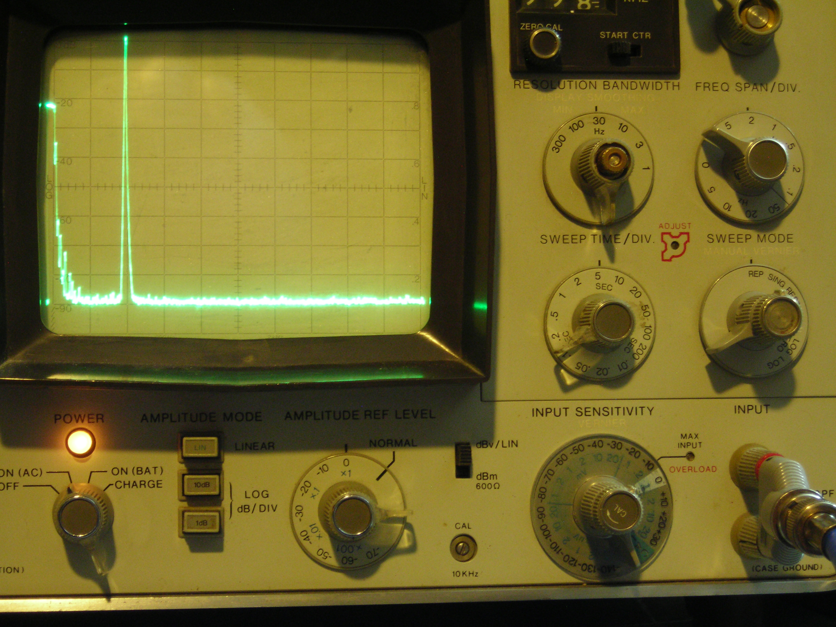
It’s not often that a single photo can tell you pretty much everything you need to know about a project, but the spectrum analyzer screenshot nearby is the perfect summary of this over-the-top low-distortion audio oscillator build. But that doesn’t mean there’s not a ton of interesting stuff going on with this one, so buckle up.
One spike at the fundamental and not much more.
The project is by [Basin Street Design], who doesn’t really offer much by way of inspiration for this undertaking, nor a discussion on what this will be used for. But the design goals are pretty clear: build an oscillator with as little distortion as possible across the audio frequency range.
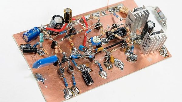
The basic circuit is the well-known Wien bridge oscillator where the R-C pairs are switched in and out of the feedback loop to achieve frequency range control. This was accomplished with rotary switches rebuilt from their original configuration in a Heathkit IG-18 sine/square wave generator, a defunct instrument that was gutted and used as an enclosure for this build. There are a lot of other treats here, too, like the automatic gain control (AGC) that uses a homebrew voltage-controlled resistor made from an incandescent lamp and a cadmium sulfide photoresistor glued inside a piece of brake line, and an output attenuator made from discrete resistors that drops the output in 10 dB steps while maintaining an overall 75-Ohm impedance.
But at the end of the day, it all comes down to that single spike on the spectrum analyzer, with no apparent harmonics. To make sure there wasn’t something hiding down in the noise, [Basin Street] added a notch filter to lower the fundamental by 60 dB, allowing the spectrum analyzer sensitivity to be cranked way up. Harmonics were visible, but so far down into the noise — as low as -115 dBc — that it’s hardly worth mentioning.
There’s a lot more detail in this one, so dive in and enjoy. If you want another take on Wien bridge circuits, check out this recent LM386-based oscillator. Just don’t expect such low distortion with that one.
If you follow audiophile reviewers, you’ll know that their stock-in trade is a very fancy way of saying absolutely nothing of quantifiable substance about the subject while sounding knowledgeable about imagined differences between devices that are all of superlative quality anyway. If you follow us, we’ll tell you that the only reviews that matter are real-world measurements of audio performance, and blind listening tests. We don’t have to tell you how to listen to music, but perhaps it’s time in our Know Audio series to look at how audio performance is measured.
Before reaching for the bench, it’s first necessary to ask just what we are measuring. What are the properties which matter in an audio chain, or in other words, just what is it that makes an audio device good?
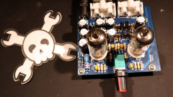
It was with considerable interest last month that I set out to track down where in the world there are still factories making tubes. My research found them in Slovakia, Russia, and China, and it’s fairly certain I didn’t find all the manufacturers by any means. There appeared to be a whole class of mundane tubes still in production that weren’t to be found on their glossy websites. A glance at any outlet through which Chinese modules can be bought will find this type of tube in small audio amplifier projects, and some of them can be astoundingly cheap. When faced with cheap electronics of course I’m tempted to buy some, so I parted with about £10 ($12.50) and bought myself a kit for a two-tube device described as a stereo preamplifier and headphone amplifier.
An Unusual Tube Choice For Audio
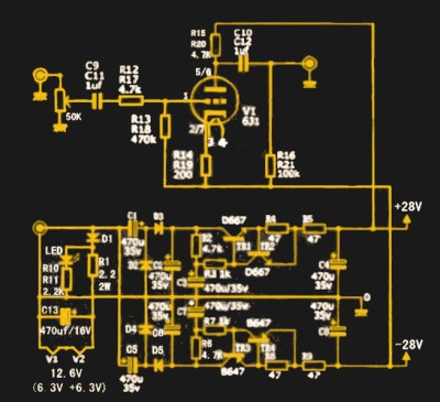
What I received for my tenner was a press-seal bag with a PCB and a pile of components, and not much else. No instructions, which would have been worrisome were the board not clearly marked with the value of each component. The circuit was on the vendor’s website and is so commonly used for these sort of kits that it can be found all over the web — a very conventional twin common-cathode amplifier using a pair of 6J1 miniature pentodes, and powered through a +25 V and -25 V supply derived from a 12 VAC input via a voltage multiplier and regulator circuit. It has a volume potentiometer, two sets of phono sockets for input and output, and the slightly naff addition of a blue LED beneath each tube socket to impart a blue glow. I think I’ll pass on that component.
The 6J1 seems to be ubiquitous throughout the Chinese kits, which is surprising when you understand that it’s not an audio tube at all. Instead it’s a small-signal VHF amplifier, a rough equivalent of the European EF95, and would be much more at home in an FM radio receiver or turret TV tuner from the 1950s. I can only assume that somewhere in China there’s a tube factory tooled up for radio tube production that is targeting this market, because another tube you will see in audio power amplifier kits is the FU32 or QQV03-20 in European parlance, a large power beam tetrode that might have been found in a 1950s military radio transmitter. Still just as if you were to use an RF transistor in an audio circuit it would give good account of itself, so it is with an RF tube. There is no reason a 6J1 won’t do an acceptable job in a circuit such as this one.
For hams who build their own radios, mastering the black art of radio frequency electronics is a necessary first step to getting on the air. But if voice transmissions are a goal, some level of mastery of the audio frequency side of the equation is needed as well. If your signal is clipped and distorted, the ham on the other side will have trouble hearing you, and if your receive audio is poor, good luck digging a weak signal out of the weeds.
Hams often give short shrift to the audio in their homebrew transceivers, and [Vasily Ivanenko] wants to change that with this comprehensive guide to audio amplifiers for the ham. He knows whereof he speaks; one of his other hobbies is jazz guitar and amplifiers, and it really shows in the variety of amps he discusses and the theory behind them. He describes a number of amps that perform well and are easy to build. Most of them are based on discrete transistors — many, many transistors — but he does provide some op amp designs and even a design for the venerable LM386, which he generally decries as the easy way out unless it’s optimized. He also goes into a great deal of detail on building AF oscillators and good filters with low harmonics for testing amps. We especially like the tip about using the FFT function of an oscilloscope and a signal generator to estimate total harmonic distortion.
The whole article is really worth a read, and applying some of these tips will help everyone do a better job designing audio amps, not just the hams. And if building amps from discrete transistors has you baffled, start with the basics: [Jenny]’s excellent Biasing That Transistor series.

 What I received for my tenner was a press-seal bag with a PCB and a pile of components, and not much else. No instructions, which would have been worrisome were the board not clearly marked with the value of each component. The circuit was on the vendor’s website and is so commonly used for these sort of kits that it can be found all over the web — a very conventional twin common-cathode amplifier using a pair of 6J1 miniature pentodes, and powered through a +25 V and -25 V supply derived from a 12 VAC input via a voltage multiplier and regulator circuit. It has a volume potentiometer, two sets of phono sockets for input and output, and the slightly naff addition of a blue LED beneath each tube socket to impart a blue glow. I think I’ll pass on that component.