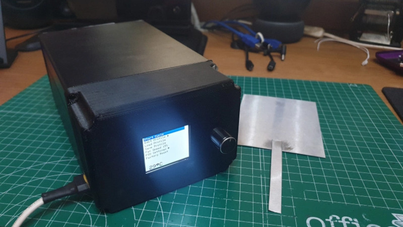
Very often, particularly on the Internet, we’re fooled into thinking bigger is always better. The fact remains that this isn’t always the case. When it comes to reflow ovens, for example if you’re working with short runs of small PCBs, or if you just don’t have a lot of space in the workshop, a smaller oven will be more desirable than a large one. It’s factors like these that drove [Sergi Martínez]’s latest build.
Built inside a metal project case, first attempts involved using an off-the-shelf heating element, with poor results. The element had a high thermal inertia, and was designed for use in water, so didn’t last in the reflow application. Learning from the experience of others, [Sergi] switched to using halogen lamps, netting much greater success. An Arduino Nano is responsible for running the show, using firmware developed by [0xPIT]. There’s also a screen for monitoring reflow profiles, and a cooling fan to help keep temperature in the ideal zone.
It’s a tidy build that would be particularly useful for quickly running batches of small PCBs without the long wait times required to heat a larger oven. Energy efficiency should be better, too. Of course, if you’re a fan of the classic toaster oven builds, we’ve got those too. Video after the break.


Does one have to worry about the vapors from the paste ruining the lamp? I know you’re not supposed to use your bare hands to touch them.
That’s a good question that I don’t have an answer for. However, I can speculate:
The problem with fingerprints on halogen bulbs is because the grease makes the glass expand and contract at a different rate to the rest of the bulb. It happens because of the elevated temperatures that halogen bulbs experience compared to non-halogen bulbs.
With that in mind, we have to ask two questions: 1. Do the solder fumes cause the change in expansion rates?; and 2. Do the fumes affect different parts of the bulb differently?
I suspect that the second question is easier to answer than the first – in any well-designed oven that answer will be no. The first question is trickier. It depends not only on the solder and flux in use at the time, but also on any previously used on the board, any adhesives in play, and potentially any compounds used in the components.
Personally, I wouldn’t worry about it. I suspect that none of the fumes would condense on the hottest part of the oven anyway. :)
1st up – halogen bulbs use pure quartz, not glass (that would not stand up to the temperature and it’s changes)
2nd – the offending crud from fingerprints seems to be alkaline compounds, that happily diffuse into it once heated and cause a change in the crystal structure…
It would probably be a good idea to check what flux does the solder paste use.
My first oven used a heat gun as a source. Cheap and circulates the air. Also, active cooling as the fan keeps bringing in fresh air. It worked well enough, never quite optimised it, if anyone wants to take it further it provides superior control and as a bonus, noise.
So its an Easy Bake oven with a color lcd…why not just go full-on nichrome wire and skip the inefficiencies of hearing with a light bulb?
All of the energy supplied to the bulb is given off as light or heat, which is the same as a nichrome wire. A typical halogen bulb is about 3.5% efficient as a light source, i.e. 96.5% of the supplied energy is given off as heat. Yes, a nichrome heating element may be more efficient heater Watt for Watt, with less light output, because it hasn’t been designed to give off light. However, the halogen lamp will burn hotter with lower thermal inertia. It does not have as big an insulator to heat, and the halogen gas allows the element to reach higher temperatures without oxidation effects causing its failure. Both of those factors are more useful in this application than another couple of percent efficiency.
The one downside of halogen bulbs versus heating elements is that they are shock-sensitive when hot. In this application that shouldn’t be a major issue though. If you’re knocking your reflow oven around when it contains an SMT PCB with melted solder then you have other problems to deal with.
Fused silica is still glass….just not your run-of-the-mill soda-lime glass.
Regarding your diffusion claim: Since Quartz Glass is chemically inert, reacting only with hydrofluoric acid, it’s a reasonable to believe that a chemical reaction isn’t the cause of a fracture. Ionic exchange within crystals aren’t reactions though. I’d question how diffusion could happen on the cool side of the glass without the halgoen and tungsten halide gases on the inner hotter side also causing diffusion problems. The answer to that is that glasses are amorphous non-crystalline solids, and that diffusion can thus be discounted.
We do know that most glass is susceptible to thermal shock when heated or cooled too quickly. That is because glass is an insulator so a thermal gradient appears, and that in conjunction with a positive temperature coefficient of expansion causes a fracture in the crystal lattice. Fused silica has an extremely low coefficient though, hence why it is used in refractory vessels and high temperature light bulbs. 1100 degree Celsius swings aren’t a problem.
However, extremely low isn’t zero. During operation, the bulb glass is heated from the inside and cooling to the outside. At thermal equilibrium a 500W T3 bulb is passing about 87W of heat through each square inch of surface area a significant heat flux. (500W * 0.965%)/(0.375″ * pi * 4.7″). The main temperature gradient within the glass is in the direction of heat transfer. Along the length of the bulb and around its circumference, the inside surface will be close to isothermic, as will its outside surface. There might be minor gradients close to the ends where the tube becomes a solid plug, but the bulbs are designed to minimize that being a problem. The heat is lost to the surrounding atmosphere via convection and radiation.
A surface contaminant changes how heat is lost to the surrounding atmosphere, and in doing so causes the contaminated section to be a different temperature than the uncontaminated surface, thus causing a temperature gradient across the surface, and that causes the fracture. I haven’t been able to find a scientific paper describing that process, but all the information that I can find (including from bulb suppliers) states that the problematic contaminants are oils from the skin, and that they cause hot spots.
I can think of 3 possible mechanisms to consider:
1. The film of oil acts as a thermal resistance reducing the ability of the contaminated section to lose heat via convection, leading to a hot spot.
2. The film of oil acts as a thermal capacitance, causing the contaminated section to lag in both heating and cooling.
3. The film of oil acts as an optical component for IR wavelengths, reflecting and refracting IR in weird ways. That would change the amount of heat lost to the atmosphere via radiation. Anyone who has seen thin films of oil on a roadway puddle after a rainstorm knows about that principle.
The likelihood is that all three effects are happening to some degree. There may be well may be other effects.
One final point. I mentioned thermal equilibrium earlier. That never actually exists in an AC bulb. The element is energized sinusoidally at 50 or 60Hz, so there is a 100 or 120Hz heating/cooling cycle happening.