Crystal radios can feel magical, given their ability to tune in audio from distant stations with nothing but the energy from the radio signal itself. However, to achieve this feat, they typically rely on a high-impedance earphone to produce an audible sound with very little current. These earphones are hard to find, and thus can be expensive. However, [Billy] figured out a way to build them on the cheap.
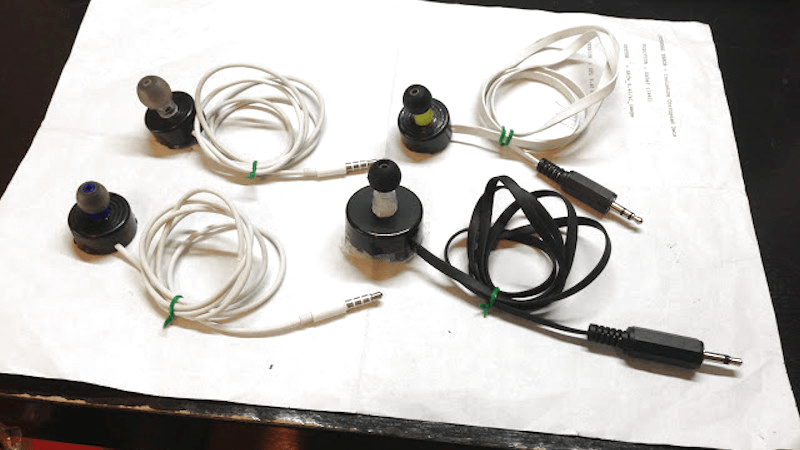
The build starts with a common piezoelectric buzzer. It’s torn down and the extraneous circuitry inside is removed. The piezo element itself is then directly hooked up to a mono audio jack for use with one of [Billy’s] crystal radios. To make it into a usable earpiece, the tip of a pen is cut off and glued to the buzzer’s plastic housing. Then, a rubber in-ear cup from regular modern earbuds is used to ensure a tight, comfortable fit in the ear.
It’s a great way to build something that’s now hard to source, and we bet that [Billy’s] design is more comfortable than the hard plastic models that shipped in Radio Shack kits in the 90s. Of course, there’s other ways to build high-impedance drivers, as we’ve featured before. And, if you’re looking to build a crystal radio, it’s hard to go past [Billy’s] credit card chip build. Video after the break.


I have a couple of those Radio Shack earphones left from kits I had in the 70s. I’ve salvaged and kept a lot of parts over the years but those are likely the oldest.
“mono audio jack”? Pretty sure jacks are female, and there’s only one mono plug in the illustration.
A “jack” is a male mule, a “jenny” is a female!
Jack rabbit, Jack the Lad, etc. Yes, it’s counter intuitive but consider mammalian anatomy. But as the terms are actually used I seem to be 50% wrong.
Crystal radio link is currently a dup of the other headphones; should be: https://hackaday.com/2020/06/01/credit-card-chip-used-to-make-crystal-radio/
It’s neat to learn how to do anything yourself, I like that.
But am I missing something? These don’t seem to be very expensive. Googling crystal radio high impedance earphone I see like half a dozen suppliers for $5-9?
Yeah perhaps you are missing the point of HAD, this hack is a welcome addition to my collection of DIY electrical components.
I don’t think r has any argument against the hack itself, just the HaD write up that asserts “These earphones are hard to find, and thus can be expensive”.
If it’s about crystal earphones, maybe they are plentiful.
But I gather that high impedance dynamic headphones may onky be availabke as used or surplus. Not much demand for those once tubes disappeared, except for crystal radios. I’ve seen people use transformers to use current “high impedance” (ie around 64ohm) headphones, but you lose in the step down.
I think I’ve read that crystal radios with headphones less than crystal (which basically have no DC load), work better, the circuit needing some lkad, but not too low. somewhere around 2000ohms I think it was.
Try this site for crystal head phones. Paul will do right by you.
http://www.modernradiolabs.com/index.html
He won’t even let you download the PDF catalog! You have to request by email. What? The site doesn’t look like it’s been changed since 1994.
If you’re listening to your local 50KW radio station, the headphones that you use aren’t critical. But if DX is your goal, you need high impedance headphones, or a matching transformer, in order to keep the Q of your LC tuning circuit high and achieve decent selectivity and sensitivity. Additionally you need to efficiently convert those picowatts of electrical energy to sound. Crystal earpieces can be good, but there are better alternatives like balanced armature headphones, but they’re not cheap.
The real problem for DX with a crystal radio is that a silicon diode will still need ~0.6 volts of signal to start conducting (i.e. “detecting”). Germanium diodes can do better (~0.3 V) but at present most of the ones with “germanium” part numbers like 1N34 are really silicon, based on the measured forward conduction drop.
At one time, GE made a “backwards diode” which was a regular diode doped so heavily that it leaked like a sieve when reverse biased so when back biased it had nearly zero “forward” drop. The usual “reverse direction” used the forward drop, so the “reverse” voltage limit was ~0.6 V. I always wanted to use one to build a crystal radio, but they were way too expensive for my hobby budget. No idea what the “real” application was.
Some modern RF diodes from companies like ADI and SkyWorks have near-zero forward voltage drop (and costs only a few bucks). I am not sure if they are suitable for crystal radio builds, though (because I’ve never built one).
How about BAT54 KL1, SOT23 Packaging SMD Schottky Diode?
I realize that some may consider this to be cheating, since a crystal radio is not supposed to use a secondary power source. But a battery, along with some series resistors and/or inductors, can be used to partially forward bias the detector diode and significantly increase the radio sensitivity. I used this technique once to make a sensitive RF detector for use with an RF sweep generator. It made the resulting plot on the ‘scope more accurate, especially at low signal levels, because the knee of the diode’s conduction curve was much sharper. Then I got a spectrum analyzer with a tracking generator and ditched the sweep generator altogether.
As for the backward diode, here’s a good explanation.
https://en.wikipedia.org/wiki/Backward_diode
As for the forward voltage drop of conventional diodes, while the knee occurs at about .7 Volts for Silicon, and about .25 Volts for Germanium, some of the natural semiconducting minerals, such as Galena (crystalline Lead Sulfide), or Iron Pyrite (Iron Sulfide) may be even lower. Consider, for example, the band-gap energies of the various semiconducting materials.
Silicon 1.12eV
Germanium .66eV
Galena .37eV
Pyrite .51eV
For materials with a higher “knee” or band-gap energy, such as Zincite or Carborundum (Silicon Carbide), it was common to use a battery to bias the detector, in order to make it more sensitive.
There are, literally, thousands of materials, or material combinations, which can be used as semiconducting detectors for crystal radios.
Note that, recently, there has been some use of zero-bias FETs configured as a diode for weak signal detection.
“Foxhole” radio projects used a double-edged razor blade and a pencil-lead to detect. I’ve tried this; it works. I also have a galena cats-whisker detector. I’ve heard that some Schottky diodes are good detectors.
I still have a small horde of pink crystal headphones, but am keen to try some like the converted piezo buzzers.