Many of Hackaday’s readers will be no stranger to surface mount electronic components, to the extent that you’ll likely be quite comfortable building your own surface-mount projects. If you have ever built a very large surface-mount project, or had to do a number of the same board though, you’ll have wished that you had access to a pick-and-place machine. These essential components of an electronics assembly line are CNC robots that pick up components from the reels of tape in which they are supplied, and place them in the appropriate orientation in their allotted places on the PCB. They are an object of desire in the hardware hacker community and over the years we’ve seen quite a few home-made examples. Their workings are easy enough to understand, but there is still much to gain by studying them, thus it was very interesting indeed to see a friend acquiring a quantity of surplus Siemens component feeders from an older industrial pick-and-place machine. A perfect opportunity for a teardown then, to see what makes them tick.
Take Me To Your Feeder
First it’s worth explaining what part a component feeder plays in a pick-and-place machine, and what it does. Components are supplied on flexible tape, sitting in depressions in its surface and covered by a thin plastic cover film that can be peeled back to reveal the part. Using sprocket holes in the edge of the tape, the feeder advances it from one part to the next while peeling back the cover to expose the part. Feeders are usually positioned in a row along the edge of the machine’s work area, such that its head can manoeuvre itself over the part and pick it up before placing it on the board. In the industrial machines this happens very quickly indeed, so the feeders are substantially built to serve many millions of parts over their lifetime.
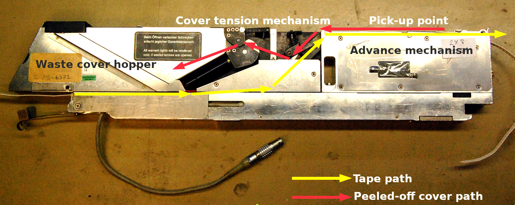
The unit is about 45 mm by 20 mm by 100 mm in size, with a very substantial machined aluminium frame upon which its various components are mounted. It holds not one but two feeders for 8 mm tape, one on either side. Turning it on its side, the front half conceals the feed mechanism with the pick-up point at the top, while at the centre is a tensioning system for the peeled-off cover tape. At the rear is a hopper for spent cover tape, accessible via a spring hatch on the back. On the top at the rear are a pair of membrane buttons, to advance or retard the tape.
The component tape enters underneath at the rear and follows a diagonal path upwards to the top, where it engages with a toothed wheel as part of the feed mechanism. The plastic cover tape is peeled back over itself and fed backwards to the tensioning system in the centre, before disappearing into its hopper. There is a solenoid-controlled shutter over the pick-up point, which is presumably opened by the machine as the pick-up head comes over it. The whole thing is designed for easy removal to be loaded with fresh tapes, so its control cables are brought out to an industrial-grade Neutrik connector.
What’s Inside The Box?
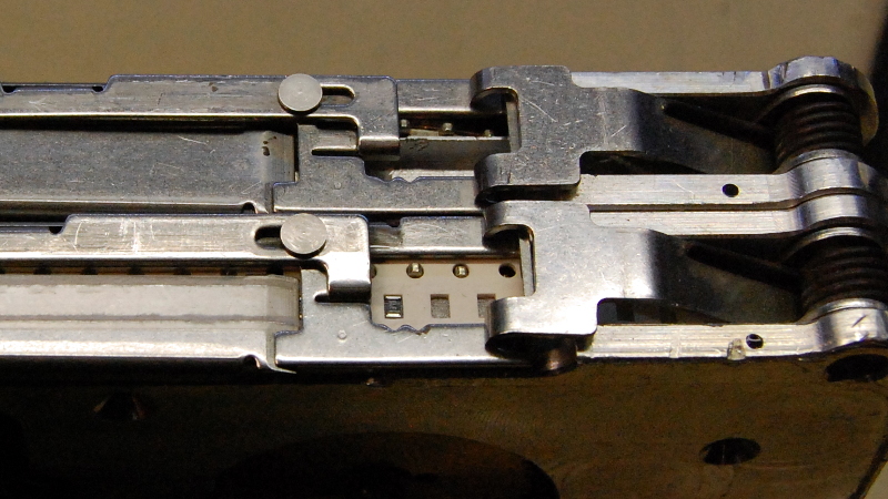
The main mechanisms are easily revealed by releasing the screws holding on their outer panels. In the front is the feed mechanism, which takes the form of a sprocket designed to engage with the holes in the tape. This is driven by a worm drive gear from a motor, which also has an optical encoder to sense how far the tape has been advanced or retarded. Above the motor is a solenoid that operates the shutter, a sliding sheet metal assembly on the top of the unit which exposes the pick-up point.


In the centre of the unit is the cover tape tension mechanism. Another motor and sprocket pulls the cover tape past a spring-tensioned roller, that has an optical sensor to feed back its position. The spent cover tape spools into the hopper at the back, from which it can be emptied upon reel changes. The whole machine is controlled by a microcontroller on a narrow PCB in the base of the unit. The guess is that it’s an older Atmel part, but for now it remains covered by a sticker. Communication with the pick-and-place machine is via a serial connection through that Neutrik connector.


What Can You Do With A Surplus Parts Feeder?
It’s been fascinating to take a look inside this feeder, but what can be done with it? In a literal sense that has an obvious answer of feeding parts to a pick-and-place machine, but the real question is: how can it be used? The interface itself is electrically straightforward, it’s a serial port that uses higher voltage differential signalling to compensate for noisy industrial machinery. The question then remains, how can they be driven, and what are the upgrades?
Happily the availability of these units on the surplus market has meant that hackers have had the chance to work on them. My friend pointed me to both a Gcode driver for them and a replacement PCB design, both on GitHub. Being a relatively easy to understand device, coming up with a way to drive them should be well within the abilities of the type of person who’s prepared to build their own pick and place machine.
A pick and place machine need not be impossible to build, but it’s certain that the component feeders are a significant part of their engineering. Maybe this look at one might shed some light on them, and introduce the option of using a surplus unit rather than attempting to build your own.


A pedant swites: Lemo, not Neutrik
Good point.
Pity I can’t type.
I am a fan of both connectors, and have used them together. Speakon work great for 3-phase power to motors, or 4 lines to big steppers. Lemo are just lovely once you get a cheap variant of the crimp tool. (the solder buckets on the fine-pitch solder ones can be miserable, though)
Here is a (sizeable) servo retrofitted with both a Lemo and a Speakon to replace some unobtanium ball-latching connectors: https://photos.app.goo.gl/6a4bP2YvbnhN5ZdQA
Thou shall not leave your measuring tools mixed with manipulation tools. Else, thou feel the rath of the elder workbench sinners and… whatever.
Damn, those big motors.
I am guessing there are standardized dimensions for the tape. Where can I find them?
I’d expect like all standards there are too many around for it to be one standard size truly fit all. I know all the tapes I’ve ever seen have be wildly different in dimensions, though the drive portion might have been standardized. Seems to me tapes can’t really be all that standard as they cover massive IC to grain of rice IC’s and smaller still passives.
I’m no expert on it though, I only pick up a few cut tape sections here and there when that is how the retailer with the component I wanted ships it. And doing all my soldering by hand I try to avoid the increasingly common tiniest sizes as they are too much damn work.
No, the tape is standardized. 8, 12, 16, 24, 32, 44, 56, 72, 88mm in width (and some larger ones perhaps), all the same sprocket pitch. Very small parts are still packaged on 8mm tape, just at shorter pitch than a large component (say, 2mm instead of 4mm or 8mm) – and that too is a standard.
Equipment manufacturers don’t want to make a special feeder for each different component on the market, and assembly houses don’t want to buy a special feeder for each part their clients want to use. Thus it makes the most sense for everyone to agree to a few standard sizes at a few standard pitches.
Source: I program and operate ASM SIPLACE equipment (what has become of the SIEMENS equipment lines from this article through a few acquisitions).
Nice to know, I figured it would be another brand cash grab, you bought our pick and place, you must use our partners tapes on them – wouldn’t be the first time such a stunt has been pulled… At least half the time it seems to stick too…
I’d imagine all that really matters is sprocket pitch, the width just had to be less than the carrier, and part interval wound be programmable
They are standarized. 8mm, 12mm, 16mm, 24mm wide (and more). Pitch is 4mm (distance between holes). Some parts (eg. 0402, 0201) are placed in pairs per one pitch.
Do a search for “Tape and Reel Specifications”.
I would post links…
But they get eaten by the spam filter on this site.
You need to start the comment with sufficient text, and then include the link(s).
Plus if you have more than one link the post just vanishes without explanation. Sometimes it shows again later on, sometimes not. Moderation maybe? I dunno, but I’d just as much suspect this flakey WordPress Jetpack comment system HaD uses.
Lorem Ipsum Dolor Sit Amet
http://google.com?q=Hackaday+Comments+Disappear
I was hoping this could be re-purposed to handle 8mm motion picture film but the pitch for the tape is 4mm whereas the pitch for standard 8mm film is 3.81mm and super 8mm film is 4.23mm
They exist and are called projectors. Fitted with optics, spools and a bright light source and were used to project a image on a flat whie surface for fun or education.
Yes, but therein lies the problem. They use sprockets and a pull-down claw resulting in a mechanism that is bulky, inaccurate and hard on film.
This is a great article, as it provides some visibility to a very critical parts of a pick and place (PnP) system that a number of smaller and home-built units ignore or simply do not consider. I say this, as I was fully unaware of all of these and other details until I bought an older PnP machine… wow, what an eye opener. It really brought home how poorly thought out and designed lower end units that are currently offered. That is not to say the lower end of home brew PnP’s are bad… but that they really do not have the reliability and capabilities to Place parts accurately, reliably, and consistently in larger volumes.
It’s indeed far from trivial to make a P&P machine work reliably and accurate, but I won’t go as far as to say it could not be home built.
I also would not say that part feeders are simply ignored or not considered.
Good part feeders are pretty complicated devices to get to work reliably, and the part feeders of “professional” machines are specifically built for reliability for big production runs but at the cost for large setup times and mandatory long leader tapes to run through the feeders.
There is a valid group of semi-professionals/hobbyists that make so much PCB’s that manual soldering becomes tedious, but production runs are not big enough to justify buying a 2nd hand P&P machine, and production runs are also too small which make setting up those machines a relatively big time consumer.
There have been a few part feeders here on Hackaday that try to address that. Small cassettes which only need a very short leader tape and can also be used as a storage box to further reduce setup times. But form what I’ve seen thus far, these probably lack in the reliability department. Some of these have bar codes, so the machine can scan where the part feeders are, which also reduces setup time.
OpenPNP can work with pieces of cut tape and a camera which looks where the cut tape is put. That can work for production runs with maybe up to 50 parts of each type.
Part feeders that work well for small batches and are small and cheap enough to also be used as storage units are still in need for some improvements.
With regards to my comments about some ignoring or not considering feeders… my point was that there is a lot going on with feeders and a number of the home made or lower end offerings simply spend their efforts on the placing part… and not so much on the picking… or better yet not picking consistently over a volume of parts. That is not to say that home brews or lower end machines are not worthy or usable, but one must really understand what their limitations are. To some these machines are sold and marketed as comparable to the higher end machines… and this could be true for doing a few boards or maybe only placing a handful of parts, but that is about it. There is certainly a reason for the cost differential between the two machine classes.
As for semi-pros or serious hobbyists that have older higher end machines… well… there is or can be a steep leaning curve to using these. Also you are quite right that setting up a machine can take a fair amount of time. However, you can obtain the best of both worlds with a bit of planning. On my machine I can load over 120 feeders and so some feeders I have already setup and pre-programmed with parts I use often (caps, resistors, etc). All that is left is the setup the additional parts. For one or two prototypes I simply place the pre-setup and often used parts and then hand populate the rest. For 10 or so boards I then setup the design’s unique parts and away it goes. I save a lot of time doing this and makes building protos or a handful of pcbs much easier and faster. I say this, as most of my designs use 200-300 parts with 30-50 that are different. So hand populating 1000 or 2000 parts over 10 or so boards gets pretty tedious. I do use a contract manufacturer for larger runs (40+), as the CM has the latest and greatest gear and so they are much faster and thus economically better for me. However, YMMV.
I am intimately familiar with these feeders. For a period of time my evening job included maintenance and repair of these feeders (and the D4 series PNP machines). Pretty solid units, most of the issues were due to build up of paper dust from the 8mm paper carrier tapes. Some units had exciting quantities of components filling every orifice – this was generally the result of operators setting the pitch wrong before running a 36 hour build and not paying attention (or even giving a shot) to the amount of components they were splicing in during the run.
While the feeders were pretty robust, we seemed to have had a few operators who were less than gentle with installing feeders and the Lemo connectors on the feeder table would end up with broken pins and then broken solder joints. Replacing the connectors sucked as the PCBs were really thick with huge ground planes, but on slow nights it was a lot more fun than listening to whatever gossip the operators wanted to talk about.
Also exciting is the waste hopper flap is just held in place with a magnet, and sufficient pressure from the cover tape build up (due to neglect by operators) would occasionally result in confetti-cannon like streamers firing off the side of the machine.
That’s fascinating, and yes I could imagine those filling up with components very easily.
Breaking a LEMO must take some effort.