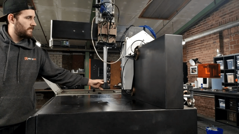
There are two paths to owning a 3D printer: purchasing one or crafting your own 3D printer designed to your own exacting specifications. [Roetz 4.0] has decided to go this latter route and converted a 1.3-ton air-bearing Coordinate-measuring machine (CMM) into an FDM 3D printer. (Video, embedded below.)
A CMM is a tool used to precisely measure the geometry of an object via gently lowering a calibrated probe. We’ve seen scratch build printers before, but this particular build benefits from having the CMM machinery and its 18 air bearings. The CMM head is moved by [Roetz 4.0]’s own custom system, but it takes advantage of the bearings. After some careful CAD planning as well as a fair bit of milling, lathing, and prototyping, he had buttery smooth controlled motion.
With an off the shelf driver board wired together with a large red button, he was ready for a maiden test print. A determination to finish before the year was out pushed things along. There are still a few quirks to fix, like the hole in the air drying system but those can be tackled next year. Ultimately, we think the results are stunning and it was a journey we were glad to go on with [Roetz 4.0]. The final episode of the series is after the break.
Thanks [Jan] for sending this one in!


I think you are on the right track. The vast majority of these additive 3D printers are surprisingly under-designed. They are open-loop devices with no way to ensure accuracy of extrusion or even basic integrity of function. Part of the problem is that they are based on a series of minimal-cost hobby systems. They need to start over wth a thorough analysis of the task and the best way to accomplish it.
Put accelerometers on the print head and the frame, and use firmware to correct everything. Ultimately a lot of the value of 3D comes from the fact that they’re as cheap and easy as regular printers, so bringing some extra quality to the low end would be great.
Also, ditch the dual z wobbly gantry design. I’ve never been impressed by the ones I’ve seen. Maybe they have better ones now, but I’m a fan of full frame box style, and only using dual z if your autolevel can keep them in sync.
But mostly, we need better firmware, and more sensors. Look at the human hand and the precision people are able to achieve. I suspect that this may actually be a good application of deep learning, to properly be able to compensate in real time without too much manual calibration.
does the Y-Deck Cartesian like the Ender 3 deal with that? or do you mean X-wobble because a lot of Ringing problems can be solved with good damping under the printer feet
Printers that put a build plate on a cantilever are really no better that a gantry design that is simple and sturdy (not all are). On the article, all I can say is that is a ton of print head mass. Ditch it and go the mosquito route or similar and speed things way up.
While current frames work- I would argue the biggest problem with good results is the bed design, and flexing frames.
With so much availability of cheap ground round stock, and waterjets everywhere, I honestly am suprised that more people don’t have serious materials for their machine.
Waterjet cut is expensive, sure, but ground rod is cheap, and could be welded into a frame that would be significantly stiff.
It’s not hard to dial in flatness of your machine when nothing flexes anywhere near current designs, because plastic components are removed as much as possible.
Hobbiests should stop fearing working in metal so much.
If you are suggesting using precision ground round stock to make rails they will need to be properly parallel – much more so that the less rigid frames, which can and will flex to make up minor deviations.
Its certainly doable, but its going to take a cunning design to allow for proper adjustment of the running surface to the structure, a degree of slop (which would be undesirable) or really high precision parts, fitted together carefully to really make gains on the simpler Al extrusion and relatively affordable linear rails of common FDM printers.
Get it right and you really will have a good machine, able to run way faster than any extruder could push molten plastic – if the steppers are beefy enough at least. Get it even slightly wrong and it will probably just bind up.
I’d also say Hobbyist and metal work doesn’t easily go together – you need a very specific type of workspace to do metal working of any sort, and a minimum kit of somewhat expensive and specialist tools you won’t use for anything else. If metal working is a big part of your making its obviously not an issue, you need those things anyway, but its tougher to step into than most other (maybe all other) avenues of making stuff.. And yes I do some metalworking myself, with rather small machine tools, and am looking at getting a nice AC TIG to work Al and thin stuff hopefully sometime this year.
I don’t thing the issue is ‘fear’ of metal so much as the fact of it being more expensive to work with due to needing a significantly different set of tools than what most people can find in their junk drawer.
If your hole making tool is a 9V cordless drill, you’re going to have a bad time if you try to drill out more than one or two accurately dimensioned and positioned holes in aluminum, not to mention steel.
A rusty old drill press you find behind a barn would do a better job, but not everyone has, wants, or has the room for a drill press.
I would definitely agree I really liked the proton open source printer from atom. It’s interesting mini cantilever design that puts the X axis and extrusion motor on the opposite side of the hot end to balance. That said, I called the machine shop I commonly used for work and sent them the prints. 6 ground rods, he suggested steel ground rods, I mentioned all I need is the rods cut and center drill on the lathe I don’t have at my shop. I’ll tap and chamfer them myself. Brace yourself. 300$ and an additional 450 to have them hardened, heat treated. Only gut part was he did say it’s practically a flat 450 so I could batch if I wanted. The only cheap material right now would be stainless. Even at that as was said above rods have a lot of surface area so lots of drag, vs a linear rail or even a v grove. The real problem is lots of you guys don’t know much about other machines and some of it doesn’t translate. I don’t say this to be mean but feedback on a printer is useless unless your machine commonly misses steps and that is a mechanic problem if you asked me. The feedback on say a mill can correct and that because it has a dynamic load on it. There are lateral forces, a lot of it. This is why mills have a solid stationary head typically and a moving bed. Well that and the mass of the bed depending on the material size obviously as mass decreases on a mill. Sure you could detect a extrusion jam but it would have to time out after a period of time as trying to correct it would just continue to skip and if it stayed stalled your just stopping the print, though that would save material. Even in industry rotory encoders are not used are often as sensorless vector control. I’d focus on the mechanical design as well. The electronics work well, well besides circles that is due to Cartesian kinematics and another discussion.
The accelerometer won’t help. Maybe you can read some vibrations, but without adequate control of the motors, theres is little you can do to cancel this vibration on open-loop systems, apart from input shaping. 3D printers next frontier is probably closed-loop motors like (proper) servos or bldc-encoder combos. Using more advanced control strategies like MPC or LQR over naive PID loops. Data-driven and deep-learning approaches are interesting and may be better, but its quite new and not ready for show time, time will tell. The thing is, the tech exists, and it has existed for a long time. Look at all these heavy duty servo-driven CNCs. Do you thing they run Marlin on their controllers? Each day is easier to ditch the stepper since open source controllers and firmwares for bldc-encoders combos like ODrive have become really good and cheap.
And yet, somehow, a lot of people are getting totally satisfactory results from them.
I very much agree – The interest in 3D printing has definitely reduced the overall costs of printers as a whole, but the negative is the market share that’s filled with “yet another 3D printer” – many are designed by people that aren’t skilled in mechanical design, controls, or productization. Kickstarter demonstrated that anyone could “grab a piece of the pie” when it comes to buzzwords like “3D printing”. Hundreds of 3D printer options became available, all promising amazing capability (never presented/proved with real world tests), and worst of all – many utilizing unique proprietary interfaces that the junior software engineer that got reeled into the project came up with (but won’t continue to develop within 6 months). The consumer-facing additive manufacturing equipment industry did indeed fail in terms of lacking direction, metrics for product comparison, and generally informing consumers. I guess that’s just what happens with “buzz technologies” – people’s eagerness to jump on board is the same eagerness that contributes to purchasing the 12th reincarnation of a mediocre 3D printer that was designed by people that understood the concepts but lack the experience required to develop something truly better than the market offerings.
I think a perfect example of this is Lulzbot. I experienced their 3D printers up through the taz 6, and each generation was total garbage piled on top of garbage, with an absolutely ludicrous price tag. I bought and Ender 3. Now every time I look at the taz I just laugh.
The only thought I disagree with you on is the fact that they are open loop. With additive manufacturing, closed loop doesn’t really seem to solve any problems. Or rather, it doesn’t fix any deficiencies without creating a slew of new problems. In a closed loop system, if the extruder were to pass its target position, it would then recover and move back to the target position – all the while dispensing liquid substrate. This creates a huge problem – material would build up at any correction site.
In the current extruder scene, it seems more straightforward to “move one step” & “dispense one unit”. You design your part in 3D, but it is then digitized – first it is obviously sliced into vertical layers, but the same sort of slicing occurs similarly in the X & Y movements within each layer.
Obviously open-loop systems with stepper motors are much more straightforward to design, but I also believe that there are other reasons open loop/stepper motors are the go-to for fabrication – whether it be 3D printers, laser cutters, CNC / router tables, etc. As long as the resolution of motor+drive assembly is more finite than the design calls for, its a straightforward way to execute positioning based processes.
That’s a good point. Although getting feedback from the sensor would be useful in correcting problems even if it’s not being corrected immediately. Although that’d require a more complex bus.
Agree closed loop isn’t a major issue, but will help on edge cases as I’d wager I’ve lost maybe as much as 1% of my prints over the years to layer shifts. There are often times that steps can be skipped leading to layer shifts. A small blob or scar (that can probably be cut or sanded out) is way better than a layer shift as even a few mm can completely ruin a print. There are fairly inexpense closed loop systems for 3D printers, Google S42B. Here’s a good demo of that: https://www.youtube.com/watch?v=eM8zSG8fEkk
Both my printers are Prusa MK3 based, but if I was running an SKR board I would definitely spend the $50 to upgrade X and Y to closed loop.
Interesting that you have experienced layer shifting as much as you have. Is it perhaps an issue of not having beefy enough motors or the stepper drivers not providing enough current? Or do you think it was a mechanical issue like a belt slipping or a pulley/coupling slipping on a motor shaft?
I’m not much of a 3D printer user, but have built several laser cutters and CNC routers. With the laser cutters I don’t think I would ever notice if I lost a step or two, as many times I can cut my part in one pass. With the CNC routers, its pretty obvious if you’re not giving the motors enough juice – A design may cut out great on one material, but trying to cut the same design out of a harder material, or trying to cut it out faster can cause the motors to lose many steps and make angry noises.
Also, I used to think stepper motor drivers were all pretty much the same, aside from various levels of micro stepping. I WAS WRONG though, and in hindsight I wasted a lot of time and money on inferior clone driver modules off amazon/ebay. Same thing with the stepper motors themselves. I imagine a lot of the crappy 3D printers flooding the marketplace are built with the absolute cheapest no-name motors, cloned driver ICs, and Arduino clones in the controllers.
Replying to DC (not sure why I can’t reply to the comment below) – but I think it’s the steppers/ belts not being designed to push through resistance as most 3D printers (including mine) are optimized for lots of light, fast moves through no resistance.
I haven’t done a straight comparison as don’t have a CNC. I have done some, mostly manual, machining at work/ way back in school. My 3D printers go way faster than I’d ever machine anything and move multiple orders of magnitude (i.e. 1000-10000x) more than mills – just think about the extra travel distance for solid layers – a 3D printer needs to cover the entire plane of the part with a 0.45mm tool.
Laser cutters don’t have this problem since they should never encounter any resistance.
CNCs have a business end literally designed to remove material. A 3D printer extruder has a lot of other stuff (like say the bed leveling sensor, part cooling fan duct, etc.) that can more easily catch on things.
Yes, the steppers/ drivers could be upgraded to ones capable of powering through any extra oozed plastic or whatever else catches and causes the printer to skip, but then the belts would probably flex/ slip. I don’t think the pulley is the problem as two grub screws, one into a flat shaft, can transfer orders of magnitude more torque than currently in the system.
While it’s definitely possible to upgrade the steppers, drivers, and say replace belts with ballscrews – we’re talking about a 10x increase in cost for a < 1% problem. Plus remember 3D prints aren't clamped down. That super beefy motion system might catch and now instead of skipping just delaminate the print from the base leading to failure anyway.
I'm aware of the big difference between drivers – here's a page with the most common 3D printer ones: https://learn.watterott.com/silentstepstick/comparison/ I have TMC2130s in my Einsy Rambo boards. Those controller boards are expensive for what they give nowadays, but I doubt my issue is counterfeit parts.
I did find this ( https://github.com/codiac2600/SKR-Bear-Marlin ) a project to get an SKR on a Prusa style machine. There's a lot of trouble in regards to the connectors, but it would theoretically let me try out the closed loop steppers on my machines as well as other types of steppers. I think I may wind up doing that at some point.
No it wouldn’t. The material is still being extruded with the assumption that the nozzle is moving along the designed path – the entire point of the closed loop is to keep the nozzle to the path better than the open loop design, which makes the “move one, extrude one” assumption closer to reality. It also eliminates the possibility of skipping steps and ruining the rest of the print because of one small slip-up that would easily sand away.
The only real criticism is that the closed loop can never eliminate the errors, so it doesn’t bring any advantages for a well designed printer that is already rigid and strong enough to never slip. It just makes the ill-designed printers work slightly better.
> closed loop doesn’t really seem to solve any problems. Or rather, it doesn’t fix any deficiencies without creating a slew of new problems.
You think so? It just works! I put on SERVO42B on all X/Y/Z/E axes and it took away steps/mm inconsistency issues, improved layer adhesion, reduced print failures overall and so on. Anyone who say closed loop mustn’t solve issues, even if they might be a real machinist, are an armchair when it comes to actually designing and BUILDING a printer through trial-and-catastrophic-errors process.
If you mean under-designed in the sense that they are not over-engineered like this build, so yes.
Yet they work surprisingly well for their price point which is the most important thing for the manufacturer and the customer.
Re: underdesigned. I used to think that too, around 2008.
Closed-loop servo control with expensive/precise/fiddly position sensing (but cheaper/faster motors!). Filament intake measurement, both width and length. Serious trammable rails with unreasonable precision.
These are all ideas that I myself have championed, at the same time maintaining a overconstrained, wobbly frame of screw rod and laser-cut acrylic.
Saying that open-loop motor control is a problem for the majority of uses is demonstrably false. I used to think so too, but a decade of experience has convinced me otherwise. That’s not where the bodies are buried.
Filament is good enough these days that compensating for width is a marginal improvement, and only when you’re really buying the cheapest stuff you can find on eBay. (Ask me how I know.)
Where we are now, at least in the consumer sphere, is kind of a middle way: cheap enough to be affordable, good enough to get the job done. It’s a truly good place. But I applaud those who want to take the extra effort too.
> That’s not where the bodies are buried.
This! Having some professional CNC experience in the past, it was also my intuition to assume that 3D printers were not rigid enough, not accurate enough, just not enough for most jobs. But I was wrong.
One of the reasons you’d want to go closed loop is probably print speed, but if that is not the constraint, I’d say: Show me your benchy!
This is my experience as well as an ME printing since the 00s on industrial machines. I thought the consumer ones were not rigid ‘enough’ until I bought one a while back and found out it was more than rigid enough for my jobs. I have Core XY machines at work. I actually think the gantry machines are better, since there is less material in my way and less joints to loosen and vibrate. Now if only the industry would realize how amateurish Benchy looks as a benchmark, and adopt real engineering based standards.
I get most of my filament from Microcenter. Typically $15/kg it’s as cheap as anything I have seen. Everything I have ever read says to at least check the diameter of each spool of filament and adjust settings accordingly. Many places I have read that it is good to check a roll again as it gets used because it might vary within the roll.
And yet, with my cheap filament I have never found any variation that I could measure. Checking it has been a complete waste of time. Maybe filament quality was a lot worse back in the early days?
Making an extrusion of consistent thickness is likely not all that hard nor expensive.
Considering that the most dirt cheap cable one can buy is still fairly uniform in thickness, all though, it is apparently much harder to ensure that the wire within remains centered, some dirt cheap cables have the conductor even leaving the insulation at times… (In short, don’t buy dirt cheap insulated wire.)
Though, I do remember times when filament were a lot less uniform…
As 3d printing is a nearly zero load operation closed loop will make basically no difference – the only thing it can do it detect and ‘fix’ when a print has curled into the print head enough to cause skipping and thus its a failed print, it might with closed loop control actually reach the end of the print and be vaguely like the object you wanted, which it wouldn’t without. But in that case it will still be a terrible output part that is probably unusable. (I suppose it might also manage to correct for a failed bearing/rail at there it might actually prove useful)
Accuracy of extrusion is an interesting one, but how would you do that practically? Pressure sensing in the melt chamber? Depth ‘camera’ on the head to scan the widths live? And is it really needed – if the filament is consistent enough there isn’t a lot to gain there, as demonstrated by everyone’s rather good prints on really cheap hardware. It is probably the one spot I’d think some feedback will really be able to gain anything though.
More rigid design so the printer can run faster and wobble less, and ‘silent’ steppers are really the only things to improve on with most cheaper FDMS printers.. Followed by lack of a heated bed and chamber for those filaments that like to warp.
Less print-head mass helps big time too. I laugh when I see humongous DD setups.
Quite right – the only reason for the moving parts to be massive is if they have to be to do the job – like the spindle on many CNC machines, its holding a 500W (or hopefully much more) motor and must resist and transmit to the frame the cutting forces.
That said the Direct Drive FDM extruders do much better with the highly flexible filaments seems to be the community consensus. As well as being able to push more plastic in many cases though I have to say I’ve never come close to trouble on that front with mine – but I understand its a bigger issue with very large nozzles, for which I’ve currently got no interest.
I have been in the CNC Machine Tool business for years. I love the fact that G Code is used in the final 3D printer feed. It is readable and easily customized from the original compiled version. So taking an off the shelf piece of equipment like this CMM and repurposing it for 3D printing is a great adaptation. In the end, all a 3D Printer is is a 3 Axis CNC machine with an extruder attached. Obviously you would’nt build a 3D Printer from scratch using expensive granite surfaces and air bearings due to price, but this build shows the beauty in being able to adapt an older piece of equipment and apply it to a newer technology. And the video is a perfect example of the phrase “The proof is in rhe pudding”!
I was thinking of adding a extrusion print head to my 3 ton CNC. Higher precision, speed, and no missed steps.
Similar situation here, except mine is like 6 tons. But in the end i figured it would need tons of work and gave up.
Nice! I’ve pondered on that idea myself, but never gone anywhere with it, mainly because I don’t have an awesome space like yours. I’m more than a little jealous.
For a first print that is pretty amazing. A little calibration and dealing with that suspected backlash (or compensating for it) should do wonders. An S-curve motion profile might help too – CMMs of that era were built for accuracy, not speed, and you’re pushing that beam back and forth pretty quick there. You might also have an opportunity to reduce the printhead mass by removing those fans and piping in compressed air instead, but the accuracy gains might be minimal. It might be worth trying that for a sleeker hotend anway.
For a heated plate, you could use an inexpensive granite surface plate. Heat and insulate 5 sides, before levelling on an insulating 3-point mount. It might take a while to heat up. Also, don’t spend money on a high grade plate – it’ll be out of spec anyway once heated. If you must chase that precision, lap it flat at operating temperature. FWIW, putting hot plastic onto the base plate is causing local high spots that are out of spec.
Lots of 3d printers could be made so much better with a cheap granite surface plate as a base instead of poorly toleranced aluminium extrusion. Even an old piece of granite counter top is likely to be an improvement in flatness, mass and stiffness. A diamond drill bit will allow anchor nuts to be epoxied in place to which components could be bolted. (Use modelling clay to dam a well of water to keep the drill bit cool, and a nylon screw in the nut when setting it). I’m surprised I haven’t seen anyone do that on HaD yet.
That’s a big waste of a precision machine.
Very True
Actually, I’d bet not.
You’d be suprised at how often old, broken, and useless CMMs come up for auction. They regularly get replaced in professional shops with newer better ones, especially when something goes mechanicaly wrong with them.
They are not designed with frames to handle milling loads, so they can’t be converted into CNC mills- but 3D printer? Absolutely.
I doubt the thing was still usable for it’s original purpose if he chose to do this.
But it’s the most functionally perfect device to be turned into a 3D printer- other than the unheated granite bed.
These are regularly scavenged for surface plates by some people, because the granite is high quality, and often comes with a grind of bolt down fasteners already installed in the granite. My previous employer did just that.
The only problem here is now more people are tuned into this and will drive up auction prices!
Yeah I’d pick one up if I had the space for such a large surface plate for that reason.. And if it comes will all the bearings might as well make it useful – tool change head and it can print and measure (automatically).. Sounds like a good project.
As for heating, well the granite is a huge thermal mass, which is inconvenient, but just lay a heated glass sheet on top with a little insulation for instance can fix that, loosing only a little bit of Z. Might even make a good candidate for a heated chamber build too – not sure how easy it would be – as fixing to granite isn’t trivial, so ideally you want to find enough points on the rest of the structure you can affix some sort air containment device. But with all the functional elements being at the very top and the hot end poking down that’s not a bad layout to start with – perhaps you just have inverted cup on the hot end shaft that slides on the table surface – will limit the print volume more significantly or stick way beyond the table at times, but it could still prove workable..
The intuition might be that FDM printing head exert no forces but just lay down liquefied material. Actually the nozzle do press down the material and exert force as sometimes show up as warps in corners and prints detaching from the bed.
OMG, all that hardware and he prints a 20mm “calibration” cube! 20mm is too small to calibrate anything unless your printer’s bed is 25x25mm. What’s next, a tugboat, baby Yoda, baby Groot? Ugh!
It’s perfect for a first print. He has a 5 digit precision set of vernier calipers, and a number of good reference surfaces. I suspect that he has a height gage and set of jo blocks too. That’s enough to get the tuning close. He wouldn’t want to wait days for massive prints to complete between tweaks.
Now, if only he had a CMM machine he could really get some accurate measurements. :D
He says its the first print so give him a pass – you really should start small, so any boneheaded mistakes you missed can be caught, safely away from the limits etc. Sure a longer calibration print and more complex benchmark will be useful later , but as the first print just getting it all moving smoothly and around the correct amount is a great start!
And ID he seems to have another identical CMM in the establishing shots.. So he probably can.
What a waste of a precision /rare CMM
A lot CMMs become so much scrap as they electronics die or software and the computers they run on do the same. Then you get to pay someone to haul the thing away because it is a pile of granite. So repurposing is a great object.
Old CMMs are anything but rare.
Hardware yes, software don’t care man. People still using mach3 out here. Tried and true. Please point me to these highly available CMMs as I’d rather have that then and oversized printer any day.
Mach 3 wont run a CMM. At least not without a lot of work.
HGR industrial has them often and even local craigslist has them. You will probably need to hire a rigger or forklift for any but the smallest ones. I have been offered them from time to time but I dont have the space or the ability to handle anything that massive.
“lathing”
The word you are looking for is turning. Lathing is putting up lath, like a lath and plaster wall.
Ah, good to see you. Where have yiu been lathely?
I mostly lurk unless I have something useful to say, been working on a spectrometer project lately, its on my hackaday.io project page.