One of the most basic and also most versatile communication interfaces on an MCU is the UART, or Universal Asynchronous Receiver/Transmitter. Usually found in the form of either a UART or USART, the former allows for pure asynchronous serial communication, whereas the latter adds flow control. When working with MCUs, they’re also one of the most common ways to output debug information.
While somewhat trickier to set up and use than a GPIO peripheral, the U(S)ART of ST’s STM32 families is fairly uncomplicated to use, and immediately provides one with an easy way to communicate in a bi-directional fashion with a device. In this article we’ll see what it takes to get started with basic UART communication on STM32 microcontrollers.
Pick One, Any One
Which USART peripheral to use does seem like a pretty easy choice especially when the lower-end STM32F0 MCUs have only two USARTs. That is, until you realize that they’re not all identical. While all support basic UART features, some add USART support, some have IrDA and Smartcard mode.
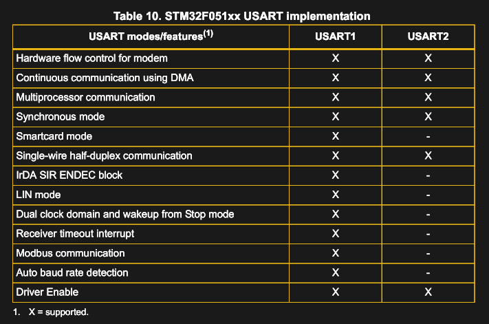
This listing from the STM32F051 datasheet shows that both of these peripherals are quite distinct, with a lot of advanced features only on the first peripheral, with the second being rather barebones in comparison. This is something that we see a lot across STM32 peripherals, not just for USARTs, but also for timers in particular. Picking the right peripheral for one’s needs can be essential, so knowing which features you need is an important skill.
For our purposes (basic UART without DMA), pretty much anything goes, but if we wanted to add a Smartcard reader feature later on, or decided that auto baud rate detection would be convenient, we would want to keep that in mind. Especially when designing for custom hardware, picking a peripheral set and associated pins for them can backfire horribly if you need to change this in a later stage, or make further development of a product significantly more complicated.
Turn It On
As with the other peripherals, at boot the USART peripheral is unpowered. To change this, we must toggle a bit in the appropriate RCC (Reset & Clock Control) register for the bus the peripheral is on. For example, if we want to use USART1 on an STM32F0 MCU, we can see that that it is found on the APB2 bus when we look at the RCC clock enable registers in the reference manual (RM) for the MCU in question, in this case RCC_APB2ENR:
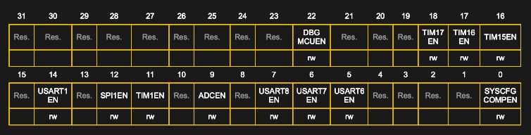
By writing a ‘1’ to bit 14, the clock domain for the USART1 peripheral will be enabled and we can use its registers. At this point, however, the peripheral is not configured and not enabled (active) yet. In order to do this, we must work through a few more steps:
- Enable the GPIO bank whose pins we want to use for communication with the outside world.
- Set the baud rate in the USART_BRR.
- Enable the USART peripheral using its internal clock register.
- Optionally configure interrupts.
Alternating Between Functions
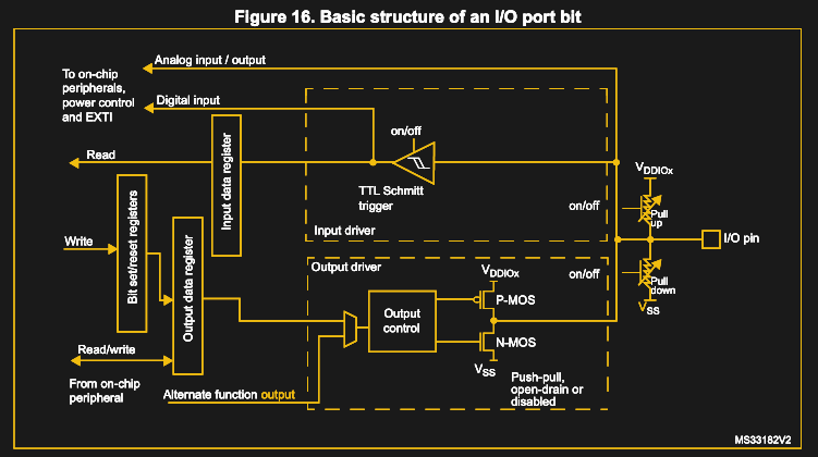
The general-purpose I/O (GPIO) peripherals do not have just one single function. As part of their ‘general-purpose’ designation they are wired up to allow for not only digital I/O, but also for connecting to the interrupt controller (EXTI) and other peripherals, including the USARTs, ADCs, DACs and so on:
Since we want to connect our USART1 peripheral to the outside world, we need to enable the Alternate Function (AF) mode on the pins we wish to use. For this we need two things:
- Which pins can be targeted by the MCU for this feature.
- A way to set this AF mode on the pin.
For STM32F0, F4, F7 and related families, this is fairly straight-forward. First we need to look at the table with the alternate function mappings in the MCU’s datasheet. For USART1 on an STM32F042 MCU, for example, we look in its datasheet (here revision 5, from 2017 from the Documentation tab) at section 4 (‘Pinouts and pin descriptions’) where in Table 14 we seen the following AF modes for port A:
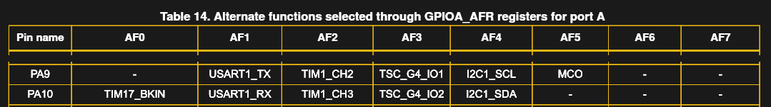
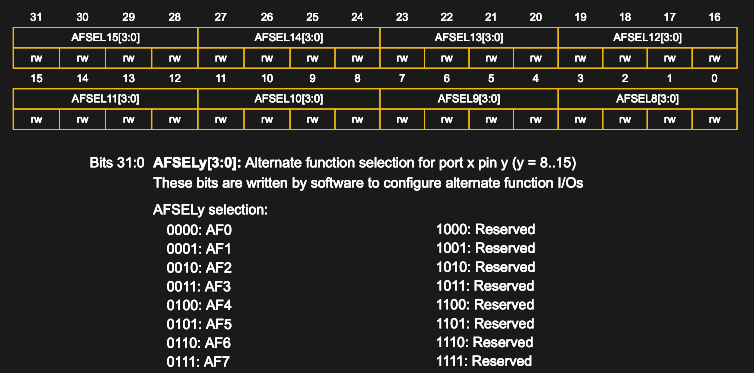
The headers labeled AF[0..7] are for Alternate Function 0 through 7. We see here that we can use our USART1’s TX and RX pins on pins 9 and 10 of port A using AF1. We now just need a way to set this, which is done using the GPIO peripheral’s AFRL and AFRH registers. This stands for ‘Alternate Function Register Low’ and ‘Alternate Function Register High’ respectively, with half of a GPIO bank’s 16 pins split over each of these registers.
Since we are interested in pins 9 and 10, we want to change the values in both AFSEL9 and AFSEL10 in GPIO_AFRH to AF1 (0x1):
With that done, we are ready to configure the USART peripheral, right after a quick note on STM32F1 AF configuration.
Beware the Leopard
While there are a lot of positive things that could be said about the STM32F1 family of MCUs, their GPIO peripherals are not among these. The reason for this becomes once again apparent when looking at configuring AF mode on a GPIO pin. Say, we wish to configure AF mode on an STM32F103 MCU, first we look in its reference manual (RM0008) at section 9.3 (‘Alternate function I/O and debug configuration (AFIO)’) and zip over to section 9.3.8 (‘USART alternate function remapping’), pick our favorite USART’s table (USART1, table 54) and get:
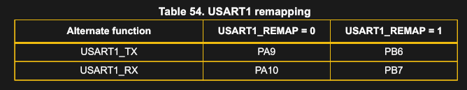
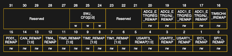
No fancy layers upon layers of Alternate Function modes here, just a curt ‘either/or’ due to the limited muxing structure on the STM32F103. Doesn’t seem too bad, right? The fun part here is that the AF functionality is not fully integrated into the GPIO peripheral, but is found in the AFIO. Glancing over at section 9.4.2 we find the AFIO_MAPR (remap register), in which we are supposed to toggle the relevant entry (USART1_REMAP):
While this may not seem much more involved than the modern STM32 approach, the annoying part here is that the AF modes are associated with the peripheral, instead of the GPIO pin. Instead of selecting an AF mode in GPIO_AFRH or GPIO_AFRL using the port, pin number and desired AF target, on the F1 MCUs you have to know the peripheral, as well as its entry position in AFIO_MAPR and what pin is associated with each of these entries and peripherals.
USART Configuration
To recap, at this point we still have to set the baud rate for the UART and enable the UART before we can even send out a ‘Hello World’. Setting the baud rate is naturally not as simple as setting the desired number in the USART_BRR register:
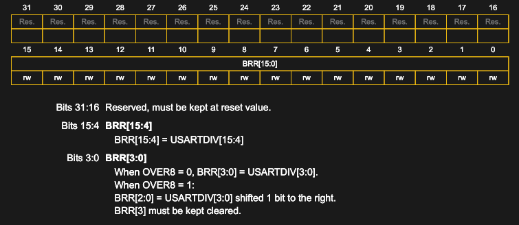
Without going into too much detail (for that see e.g. 27.5.4 in RM0091), the simple way to fill in this register without changing the default settings (like enabling OVER8 in USART_CR1), is to divide the system core clock by the desired baudrate, then dividing this by 16 twice, first to get the integer fraction and then using a modulo operation to get the remainder (incorrectly called the ‘mantissa’ by ST).
In code:
uint16_t uartdiv = SystemCoreClock / baudrate;
instance.regs->BRR = (((uartdiv / 16) << USART_BRR_DIV_MANTISSA_Pos) |	((uartdiv % 16) << USART_BRR_DIV_FRACTION_Pos));
Here baudrate is the desired baudrate (e.g. 9600) and SystemCoreClock is the core system clock speed in Hz. Using the position of the ‘mantissa’ and ‘fraction’ positions in USART_BRR their values are bit-shifted into an integer value that is then written to the register.
With all of the hard work done, we can now enable the USART. This is done in the USART_CR1 register:
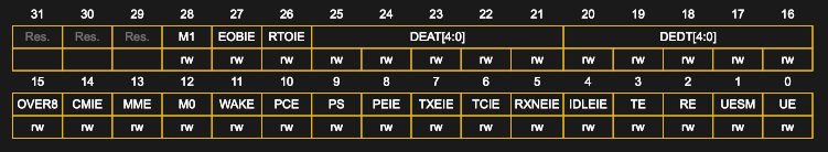
The bits to toggle to ‘1’ here are RE (Receive Enable), TE (Transmit Enable), UE (USART Enable) and RXNEIE (RXNE Interrupt Enable). The last one enables the generation of an interrupt whenever new data arrives and is optional for basic UART operation. At this point we should be able to send and receive data, by writing into, or reading from GPIO_DR, respectively.
Time To Say ‘Hi’
Central to sending and receiving data with a UART is the USART_SR (Status Register):
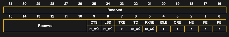
The bits to look out for here are:
- TXE (Transmit data register empty).
- RXNE (Receive data register not empty).
The first (TXE) is to be checked every time that we wish to send a byte:
while (!(instance.regs->SR & USART_SR_TXE)) {};
instance.regs->DR = (uint8_t) ch;
Vice versa, to read we need to check the latter (RXNE) to know that data is available for reading:
if (instance.regs->SR & USART_SR_RXNE) {
    rxb = instance.regs->DR;
    instance.callback(rxb);
}
These code snippets were taken from the USART class in the Nodate framework.
Wrapping Up
Being able to receive and send single bytes in this manner is not exactly the optimal way to use a UART. In upcoming articles we will look at adding interrupts, DMA transfers and control flow (USART) and more to make full use of the versatility of these USART peripherals.
Although deceptively simple at their core, USARTs can be considered to be a Swiss Army knife of communication peripherals. They work just about everywhere and can be adapted to a wide variety of tasks, whether one needs to hook up sensors, provide a user interface, control industrial equipment, or something more exotic. Hopefully this article gave a first glimpse of these possibilities.


Opening paragraph gets USART definition wrong. It doesn’t add handshake lines. Primary difference over async is that a clock is provided, either separately, or combined with the data (manchester encoding, NRZI, etc).
This is not a criticism of the main topic, which appears to be covered well.
The difference between a UART and a USART is not hardware flow control. A UART may also support hardware flow control. The USART enables synchronous protocols, instead of just the asynchronous protocols a pure UART allows. Asynchronous protocols require each character to be surrounded by a start bit and at least one stop bit. Synchronous character protocols begin transmission with one or more SYN characters to establish synchronization, followed by an uninterrupted stream of bytes without start and stop bits. The byte stream may have extra signal transitions or extra synchronization characters automatically inserted and removed in the case of long strings of ones or zeroes, so that bit and byte synch are not lost. The USART may also rely on a separate signal from a modem to clock the data.
It’s all very simple, really–
UART: U(niversal) ASYNCHRONOUS R(eceiver)-T(ransmitter)
USART: U(niversal) SYNCHRONOUS / ASYNCHRONOUS R(eceiver)-T(ransmitter)
********************************************************************************************
The integrated-circuit UART was originally developed to replace–in some cases–an entire board of components (as implemented by some minicomputer manufacturers) to drive the strictly–by inherent design–asynchronous, 110-baud Baudot-code (one start bit; eight data bits; two stop bits) teletype machine which was THE ONLY I/O device for minicomputers back then. It was developed in a ‘bet-the-farm’ type effort for Digital Equipment Corporation (one of the largest minicomputer manufacturers, then) by a ‘no-name’ electronics venture, called Western Digital.[historic note: the original Baudot code was only five bits; ‘modern teletypes’, of the type used by DEC, and all others until the end of the ‘teletype days’, used eight bits for a much richer character set]
The USART was a later, much more capable evolutionary progression of the UART which could, in addition to providing the UART function, provide for synchronous transmission in order to achieve higher speeds than are available with purely asynchronous methods.
USART is able to input/output separate clock signal, UART must be synchronized in-band.
Thanks for the guidance.
Yes, I appreciate that high density information like a data sheet is also available in light digestibility form.
And yes, my (unreasonable?) fear for the size of STM32 data sheets remains :-/