Replacement LED Light Build Uses A Few Tricks

Microscopes have become essential work bench tools for hackers, allowing them to work with tiny SMD parts for PCB assembly and inspection. Couple of years back, mad scientist [smellsofbikes] picked up a stereo microscope from eBay. But its odd-sized, 12 volt Edison-style screw base lamp, connected to a 17 volt AC supply, burned off after a while. He swapped the burnt lamp with the spare, which too blew up after some time. Dumb lamps. Maybe the original spec called for 24 volt lamps, which were unobtanium due to the odd Edison screw base, but those would throw out a pretty yellow-orange glow. Anyhow, for some time, he worked with a jury-rigged goose neck lamp, but frequently moving the microscope and the lamp was becoming a chore. When he got fed up enough about it, he decided to Build a Replacement LED Microscope Light.

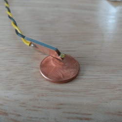
Usually, such builds are plain vanilla and not much to write in about, but [smellsofbikes] has a few tricks worth taking note of. He found a couple of high power, SMD LEDs in his parts bin. They were just slightly wider than 1.6 mm across the terminals. So he took a piece of double sided, copper clad FR4, and edge mounted the LED against one side of the PCB piece, twisting it slightly so he could solder both terminals. This works as a great heat sink for the LED while still having a very narrow profile. This was important as the replacement LED board had to fit the cylinder in which the original lamp was fitted.

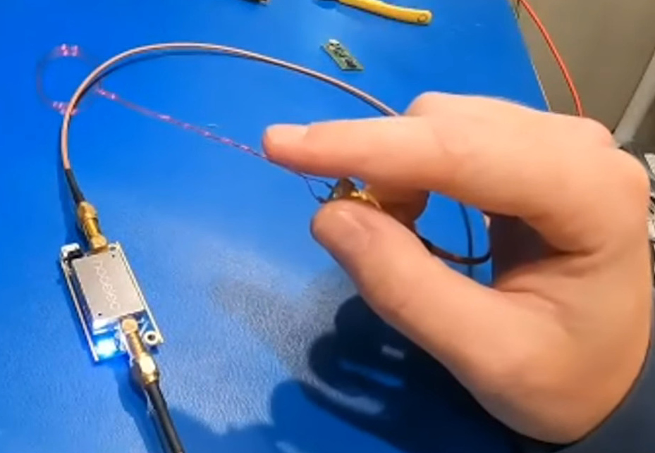
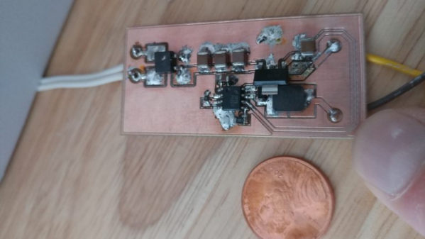
The LED is driven by a constant current buck regulator, powered by the original 17 volt transformer. A bridge rectifier and several filter capacitors result in a low ripple DC supply, for which he used the KiCad spice functionality to work out the values. The LM3414 driver he used is a bit off the beaten track. It can run LEDs up to 60 watts at 1 amps and does not require an external current sense resistor. This was overkill since he planned to run the LED at just 150 mA, which would result in a very robust, long lasting solution. He designed the driver PCB in KiCad, and milled it on his LPKF circuit board plotter. The nice thing with CNC milled PCBs is that you can add custom copper floods and extend footprint pads. This trick lets you solder either a 0805 or a 1206 part to the same footprint – depending on what you can dig up from your parts bin.

Continue reading “Replacement LED Light Build Uses A Few Tricks”

Learning To Speak Peloton

Recently [Imran Haque]’s family bought the quite popular Peloton bike. After his initial skepticism melted to a quiet enthusiasm, [Imran] felt his hacker curiosity begin to probe the head unit on the bike. Which despite being a lightly skinned android tablet, has a reputation for being rather locked down. The Peloton bike will happily collect data such as heart rate from other devices but is rather reticent to broadcast any data it generates such as cadence and power. [Imran] set out to decode and liberate the Peleton’s data by creating a device he has dubbed PeloMon. He credits the inspiration for his journey to another hacker who connected a Raspberry Pi to their bricked exercise bike.

As a first step, [Imran] step began with decoding the TRRS connector that connects the bike to the head unit. With the help of a multi-meter and a logic analyzer, two 19200bps 8N1 RS-232 channels (TX and RX) were identified. Once the basic transport layer was established, he next set to work decoding the packets. By plotting the bytes in the packets and applying deductive reasoning, a rough spec was defined. The head unit requested updates every 100ms and the bike responded with cadence, power, and resistance data depending on the request type (the head unit did a round-robin through the three data types).

Once the protocol was decoded, the next step for [Imran] was to code up an emulator. It seems a strange decision to write an emulator for a device with a simple protocol, but the reasoning is quite sound. It avoids a 20-minute bike ride every time a code change needs to be tested. [Imran] wrote both an event-driven and a timing-accurate emulator. The former runs on the same board as the PeloMon and the latter runs on a separate board (an Arduino).

The hardware chosen for the PeloMon was an Adafruit Feather 32u4 Bluefruit LE. It was chosen for supporting Bluetooth LE as well as having onboard EEPROM. A level shifter allows the microcontroller to talk directly to the RS-323 on the bike. After a few pull requests to the Adafruit Bluetooth libraries and a fair bit of head-banging, [Imran] has code that advertises two Bluetooth services, one for speed and another for power. A Bluetooth serial console is also included for debugging without having to pull the circuit out.

The code, schematics, emulators, and research notes are all available on GitHub.

Helping Hands, Reinvented

[Nixie] was tired of using whatever happens to be around to hold things in place while soldering and testing. It was high time to obtain a helping hands of some kind, but [Nixie] was dismayed by commercial offerings — the plain old alligator clips and cast metal type leave a lot to be desired, and the cooling tube cephalopod type usually have the alligator clips just jammed into the standard tube ends with no thought given to fine control or the possibility of reducing cable count.

[Nixie] happened to have some unneeded cooling tube lying around and started designing a new type of helping hands from the ground plane up. Taking advantage of the fact that cooling tubes are hollow,  [Nixie] routed silicone-jacketed wires through them for power and low speed signals. These are soldered to five banana jacks that are evenly spaced around an alligator clip.

Even if you don’t need power, all those extra alligators would come in quite handy for circuit sculpture or anything else that requires a lot of hands. [Nixie] put the files up on Thingiverse if you want to make your own.

We’ve seen plenty of helping hands over the years, but this concrete-based helper ought to cement your decision to make your own.

Old Kindle Shows HDMI Video, Eventually

Even with the recent price reductions on stand-alone panels, picking up a used Kindle is still arguably the most cost effective way to get your hands on a large electronic paper display. Especially when you consider the Kindle includes a battery, case, and electronics to drive the display. Bending the Kindle software to your whims introduces its own unique challenges of course, but with a little tweaking, an old e-reader can live again as whatever you wish it to be.

Case in point, the OkMonitor project by [Brendan Sleight]. Using a somewhat dizzying combination of software and hardware, he’s figured out a way to turn an older Kindle Paperwhite into a plug-and-play HDMI monitor. Is it a great monitor? Far from it. As the name implies, the best you can hope to get from this solution is an OK monitor. But at least it’s something.

There’s quite a bit going on behind the scenes in OkMonitor, which [Brendan] describes through a slideshow on the project page. But the high-level idea is that a Raspberry Pi 4 with a simple USB HDMI capture device takes the video input and converts it on the fly to a scaled down Kindle-friendly format. The converted video is streamed over WiFi to the jailbroken Kindle with netcat, where it’s displayed by a native video player. In the video after the break you can see that the end result looks pretty impressive, even if there is a considerable delay involved.

Despite the demonstration [Brendan] has put together for OkMonitor, we can’t say we’d watch many films over this setup. But the fact that you can plug any HDMI device into the “base station” and have the video sent out to one or more Kindles is undeniably impressive. It’s definitely worth a close look, even if you just take some of the concepts of this project to get your own Kindle repurposing idea off the ground.

We’ve recently seen some promising progress made towards repurposing large e-paper price tags labels, but it’s hard to imagine such niche devices will ever become cheaper than second hand Kindles. With continued software development, these old e-readers are likely to remain quite popular among hackers.

Continue reading “Old Kindle Shows HDMI Video, Eventually”

Remoticon Video: Basics Of RF Emissions Debugging Workshop

These days we’re surrounded by high-speed electronics and it’s no small feat that they can all play nicely in near proximity to each other. We have RF emissions standards to thank, which ensure new products don’t spew forth errant signals that would interfere with the data signals traveling through the ether. It’s long been the stuff of uber-expensive emissions testing labs, and failure to pass can leave you scratching your head. But as Alex Whittimore shows in this workshop from the 2020 Hackaday Remoticon, you can do a lot of RF emissions debugging with simple and inexpensive tools.

Professionally-made probes in several sizes
Build your own probes from magnet wire

You can get a surprisingly clear picture of what kind of RF might be coming off of a product by probing it on your own workbench. Considering the cost of the labs performing FCC and other certifications, this is a necessary skill for anyone who is designing a product headed to market — and still damn interesting for everyone else. Here you can see two examples of the probes used in the process. Although one is a pack of professional tools and other is a bit of enameled wire (magnet wire), both are essentially the same: a loop of wire on which a magnetic field will induce a very small current. Add a Low-Noise Amplifier (LNA) and you’ll be up and measuring in no-time.

I really enjoyed how Alex started his demo with “The Right WayTM” of doing things — using a proper spectrum analyzer to visualize data from the probes. But the real interesting part is “The Hacker WayTM” which leverages an RTL-SDR dongle and some open-source software to get the same job done. Primarily that means using SDRAngel and QSpectrumAnalyzer which are both included in the DragonOS_LTS which can be run inside of a virtual machine.
Continue reading “Remoticon Video: Basics Of RF Emissions Debugging Workshop”

Bare-Metal STM32: Universal, Asynchronous Communication With UARTs

One of the most basic and also most versatile communication interfaces on an MCU is the UART, or Universal Asynchronous Receiver/Transmitter. Usually found in the form of either a UART or USART, the former allows for pure asynchronous serial communication, whereas the latter adds flow control. When working with MCUs, they’re also one of the most common ways to output debug information.

While somewhat trickier to set up and use than a GPIO peripheral, the U(S)ART of ST’s STM32 families is fairly uncomplicated to use, and immediately provides one with an easy way to communicate in a bi-directional fashion with a device. In this article we’ll see what it takes to get started with basic UART communication on STM32 microcontrollers.

Continue reading “Bare-Metal STM32: Universal, Asynchronous Communication With UARTs”

Hackaday Podcast 100: Arduino Plays CDs, Virtual Reality In The 60s, And Magical Linear Actuators

Hackaday editors Elliot Williams and Mike Szczys kick off the first episode of the new year with the best hacks the internet has to offer. There’s a deep dive into water-level sensing using a Christmas tree as an excuse. We ooh and ah over turning a CD-ROM drive into a CD player (miraculous tech of the previous century?). Do you have any use cases for ATtiny oscillator calibration registers? We look in on a hack that makes it dead simple to measure and set their values. The episode finishes up with a discussion of the constantly moving goal posts of virtual reality.

Take a look at the links below if you want to follow along, and as always, tell us what you think about this episode in the comments!

Direct download (~65 MB)

Places to follow Hackaday podcasts:

Continue reading “Hackaday Podcast 100: Arduino Plays CDs, Virtual Reality In The 60s, And Magical Linear Actuators”